The Future of Orthopedics: 3D-Printed Synthetic Bone Graft Scaffolds for Enhanced Healing
This article provides a comprehensive overview of 3D printing technologies for synthetic bone graft scaffolds, targeting researchers and biomedical professionals.
The Future of Orthopedics: 3D-Printed Synthetic Bone Graft Scaffolds for Enhanced Healing
Abstract
This article provides a comprehensive overview of 3D printing technologies for synthetic bone graft scaffolds, targeting researchers and biomedical professionals. It explores the fundamental materials like bioceramics and polymers, details advanced manufacturing methodologies such as digital light processing and extrusion-based bioprinting, and addresses critical challenges in scaffold design and mechanical properties. The content further examines rigorous validation techniques, including in vitro bioactivity assays and comparative analyses with traditional autografts and allografts. The synthesis aims to bridge current research with future clinical applications in personalized bone regeneration.
From Materials to Models: The Science Behind 3D-Printed Bone Scaffolds
Application Notes
This document provides application notes and experimental protocols for core biomaterials used in the 3D printing of synthetic bone graft scaffolds. These scaffolds are critical for bone tissue engineering, addressing limitations of autografts and allografts.
Hydroxyapatite (HA)
Hydroxyapatite (Ca₁₀(PO₄)₆(OH)₂) is a calcium phosphate ceramic that mimics the mineral phase of natural bone (~70 wt%). Its key properties include excellent osteoconductivity, bioactivity (forming a direct bond with bone), and slow in vivo degradation. However, its brittleness and slow degradation rate necessitate composite formation.
Primary Applications in 3D Printing:
- Binder Jetting: HA powder is bound layer-by-layer using a polymeric binder.
- Direct Ink Writing (DIW): HA is incorporated into a shear-thinning hydrogel or paste for extrusion.
- Selective Laser Sintering (SLS): HA-polymer composite powders are fused using a laser.
- Stereolithography (SLA): HA is suspended in a photocurable resin.
Tricalcium Phosphate (TCP)
TCP exists in two crystallographic forms: α-TCP and β-TCP. β-TCP (Ca₃(PO₄)₂) is more commonly used due to its greater stability and controlled biodegradability (6-18 months). It is more soluble than HA and actively participates in bone remodeling, being resorbed by osteoclasts and replaced by new bone.
Primary Applications in 3D Printing:
- Often used in biphasic calcium phosphate (BCP) composites with HA to tailor degradation rates.
- Extruded as a paste with biodegradable polymers.
- Processed via SLS with polycaprolactone (PCL) to create strong, resorbable scaffolds.
Bioactive Polymers
This class includes natural and synthetic polymers that facilitate bioactivity and provide tailored mechanical/ degradation properties.
- Natural: Collagen, chitosan, alginate, hyaluronic acid. Provide cell-recognition sites but have variable properties.
- Synthetic: Polycaprolactone (PCL), polylactic acid (PLA), poly(lactic-co-glycolic acid) (PLGA). Offer predictable mechanical strength and degradation kinetics (weeks to years).
Primary Applications in 3D Printing:
- PCL/PLA/PLGA: Widely used in Fused Deposition Modeling (FDM) and SLS for structural support.
- Gelatin/Alginate: Used in DIW and bioprinting at low temperatures to encapsulate cells.
- Photopolymers (e.g., PEGDA): Used in SLA/DLP, often combined with HA/TCP particles to create bioactive, precise scaffolds.
Quantitative Comparison of Core Biomaterial Properties
Table 1: Key Properties of Core Biomaterials for 3D-Printed Bone Scaffolds
| Property | Hydroxyapatite (HA) | β-Tricalcium Phosphate (β-TCP) | Polycaprolactone (PCL) | Polylactic Acid (PLA) |
|---|---|---|---|---|
| Chemical Formula | Ca₁₀(PO₄)₆(OH)₂ | Ca₃(PO₄)₂ | (C₆H₁₀O₂)ₙ | (C₃H₄O₂)ₙ |
| Degradation Rate | Very Slow (>2-3 years) | Moderate (6-18 months) | Slow (2-4 years) | Moderate (months - 2 years) |
| Compressive Strength (MPa) | 30-300 (Dense) | 20-100 (Dense) | 10-50 | 45-70 |
| Young's Modulus (GPa) | 70-120 | 30-100 | 0.2-0.5 | 3-4 |
| Osteoconductivity | Excellent | Excellent | Poor (unless composite) | Poor (unless composite) |
| Primary 3D Printing Use | Binder Jetting, SLA, DIW | DIW, SLS (with polymer) | FDM, SLS | FDM |
| Key Advantage | High bioactivity & bonding | Biodegradable, remodeled | Ductile, long-term support | Good strength, FDA-approved |
Table 2: Typical Composition & Performance of 3D-Printed Composite Scaffolds
| Composite Formulation | 3D Printing Method | Porosity (%) | Compressive Strength (MPa) | Key Outcome (In Vivo) |
|---|---|---|---|---|
| HA/Collagen Paste | Direct Ink Writing | 60-70 | 2-10 | Enhanced osteogenesis vs. pure HA. |
| β-TCP/PCL (60/40 wt%) | Selective Laser Sintering | 50-60 | 8-15 | Balanced degradation & bone formation at 12 weeks. |
| HA/PLGA Microspheres | Fused Deposition Modeling | 40-50 | 20-40 | Sustained drug release, good bone ingrowth. |
| PEGDA-HA (20 wt%) | Stereolithography | 70-80 | 5-20 | High precision, excellent cell seeding. |
Experimental Protocols
Protocol 1: Direct Ink Writing (DIW) of a β-TCP/Alginate Composite Scaffold
Aim: To fabricate a biodegradable, osteoconductive scaffold with defined architecture.
Materials:
- β-TCP powder (particle size < 10 µm)
- Sodium alginate powder
- Calcium chloride (CaCl₂) dihydrate
- Deionized water
- DIW 3D printer with pneumatic extrusion system and nozzle (250-400 µm diameter)
- CAD model of scaffold (e.g., 0/90° lattice)
Procedure:
- Ink Preparation: Prepare a 4% (w/v) sodium alginate solution in deionized water. Mix β-TCP powder into the alginate solution at a 40% (w/v) loading ratio. Stir vigorously (2 hrs) and then degas under vacuum to remove air bubbles.
- Printer Setup: Load the ink into a syringe barrel. Attach the nozzle. Set pneumatic pressure (20-35 psi) and print speed (5-10 mm/s) via printer software.
- Crosslinking Bath Preparation: Prepare a 2% (w/v) CaCl₂ solution in a Petri dish.
- Printing: Initiate printing layer-by-layer into the CaCl₂ bath for immediate ionic crosslinking of alginate.
- Post-Processing: After printing, immerse the scaffold in fresh CaCl₂ solution for 10 minutes for complete crosslinking. Rinse gently with DI water.
- Characterization: Analyze scaffold morphology via SEM, measure compressive strength, and conduct in vitro degradation in simulated body fluid (SBF).
Protocol 2:In VitroBioactivity Assessment in Simulated Body Fluid (SBF)
Aim: To evaluate the apatite-forming ability (bioactivity) of a 3D-printed scaffold.
Materials:
- 3D-printed scaffold samples (HA, TCP, or composite)
- Reagents to prepare SBF (NaCl, NaHCO₃, KCl, K₂HPO₄·3H₂O, MgCl₂·6H₂O, CaCl₂, Na₂SO₄, Tris buffer)
- Incubator at 36.5°C
- Scanning Electron Microscope (SEM) with EDS
- X-ray Diffractometer (XRD)
Procedure:
- SBF Preparation: Prepare SBF according to Kokubo's protocol, ensuring ion concentrations equal to human blood plasma. Adjust pH to 7.40 at 36.5°C using Tris buffer and HCl.
- Immersion: Place each sterile scaffold sample in a separate container with a volume of SBF 10x the sample's surface area. Incubate at 36.5°C for periods of 1, 7, and 14 days. Replace SBF every 48 hours.
- Sample Retrieval: At each time point, remove samples, rinse gently with DI water, and dry at room temperature.
- Analysis:
- SEM/EDS: Image the surface morphology. Look for a cauliflower-like apatite layer. Perform EDS to confirm Ca/P ratio (~1.67).
- XRD: Identify crystalline phases. Look for characteristic hydroxyapatite peaks (e.g., at 2θ ≈ 26° and 32°) emerging on the material surface.
- Interpretation: Formation of a bone-like apatite layer indicates high bioactivity, predicting direct bonding with bone in vivo.
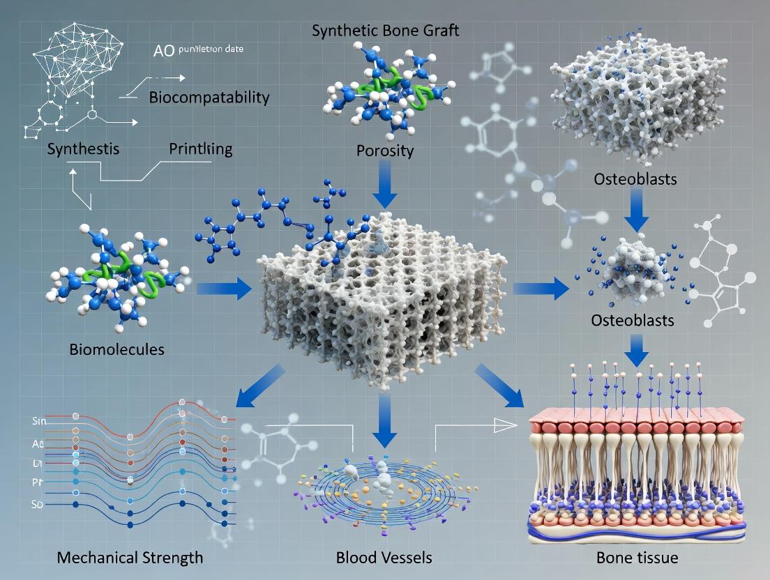
Visualizations
Title: Thesis Workflow for 3D Printed Bone Scaffolds
Title: Osteogenic Signaling Pathway on Bioactive Scaffolds
The Scientist's Toolkit: Research Reagent Solutions
Table 3: Essential Materials for 3D Printing Bone Scaffold Research
| Item / Reagent | Function / Application | Key Consideration |
|---|---|---|
| β-TCP Powder (< 50 µm) | Primary osteoconductive ceramic for DIW or SLS inks. | Purity (>98%) and particle size distribution affect printability & bioactivity. |
| Medical Grade PCL Pellet | Synthetic polymer for FDM or SLS; provides structural integrity. | Molecular weight (e.g., 50-80 kDa) dictates melt viscosity & degradation rate. |
| Sodium Alginate (High G) | Natural polymer for DIW; provides shear-thinning and ionic crosslinking. | Guluronic acid (G) content determines gel strength and stability. |
| Polyethylene Glycol Diacrylate (PEGDA, MW 700) | Photocurable resin for SLA; can be blended with ceramic particles. | Degree of functionalization and molecular weight control crosslink density. |
| Simulated Body Fluid (SBF) Kit | Standardized solution for in vitro bioactivity (apatite formation) testing. | Must follow Kokubo protocol precisely for reproducible results. |
| Cell Culture Media (α-MEM) | For in vitro osteoblast seeding and proliferation studies on scaffolds. | Supplements (FBS, ascorbic acid, β-glycerophosphate) are required for differentiation. |
| AlamarBlue or MTS Assay Kit | Colorimetric assay for quantifying cell viability and proliferation on scaffolds. | Requires standard curve and careful removal of unreacted dye from porous scaffolds. |
| Osteogenic Antibody Panel (Runx2, OPN, OCN) | For immunofluorescence staining to confirm osteogenic differentiation of cells. | Requires optimized permeabilization and blocking for 3D scaffold structures. |
Within the broader thesis on 3D printing of synthetic bone graft scaffolds, the dual rationale of achieving patient-specific geometry and controlled porosity is paramount. Patient-specific geometry, derived from clinical CT/MRI scans, ensures an anatomical fit and mechanical stability at the implant site, enhancing osteointegration. Controlled porosity, dictated by scaffold design and printing parameters, directly influences critical biological outcomes: pore size, interconnectivity, and strut architecture govern vascular ingrowth, nutrient diffusion, and stem cell differentiation. This synergy addresses the limitations of off-the-shelf grafts by creating biomimetic, bioactive constructs that can be further functionalized with drugs or growth factors for enhanced bone regeneration.
Key Experimental Data & Comparative Analysis
Table 1: Influence of 3D Printing Parameters on Scaffold Porosity and Mechanical Properties
| Printing Technology | Material | Pore Size (µm) | Porosity (%) | Compressive Modulus (MPa) | Key Biological Outcome (e.g., Cell Viability, Osteogenesis) |
|---|---|---|---|---|---|
| Extrusion-based | PCL/β-TCP Composite | 350 - 500 | 60 - 70 | 40 - 120 | Enhanced osteogenic differentiation of hMSCs in vitro |
| SLA/DLP | PEGDA/Hydroxyapatite | 200 - 400 | 50 - 65 | 150 - 300 | High cell seeding efficiency (>85%) and neovascularization |
| SLS | PCL | 400 - 700 | 70 - 80 | 10 - 50 | Favorable for rapid vascular invasion in vivo |
| Inkjet (Binder Jetting) | Calcium Sulfate/Phosphate | 100 - 300 | 40 - 55 | 5 - 20 | Excellent biodegradation matching new bone formation |
Table 2: Clinical & Pre-Clinical Outcomes of Patient-Specific 3D-Printed Scaffolds
| Anatomical Site | Study Type | Follow-up Period | Key Metric | Result with 3D-Printed Scaffold vs. Control |
|---|---|---|---|---|
| Craniofacial Defect | Pre-clinical (Ovine) | 6 months | Bone Volume/Tissue Volume (BV/TV) (%) | 58.2 ± 5.1 vs. 32.4 ± 4.8 (Allograft) |
| Mandibular Reconstruction | Clinical Case Series | 12 months | Implant Stability Quotient (ISQ) | 72.5 ± 3.2 (indicating successful load-bearing integration) |
| Tibial Segmental Defect | Pre-clinical (Rabbit) | 8 weeks | Angiogenesis (Vessels per mm²) | 12.3 ± 1.5 vs. 6.8 ± 1.2 (Porous Commercial Implant) |
| Spinal Fusion | In vitro Model | N/A | ALP Activity (nmol/min/µg protein) | 2.8x increase on graded porosity scaffold vs. uniform |
Detailed Experimental Protocols
Protocol 3.1: Design and Fabrication of a Patient-Specific, Graded Porosity Scaffold
Objective: To fabricate a biodegradable composite scaffold with anatomically accurate geometry and regionally varied porosity to direct cell behavior.
Materials:
- Medical CT scan data (DICOM format)
- CAD/Scaffold design software (e.g., 3D Slicer, Meshmixer, nTopology)
- Biopolymer (e.g., PLLA, PCL)
- Ceramic powder (e.g., nano-hydroxyapatite, β-TCP)
- Solvent (e.g., Chloroform for PCL)
- Extrusion-based 3D Bioprinter (e.g., Allevi 3, BIO X) with heated syringe
- Fume hood, vacuum desiccator.
Methodology:
- Image Segmentation & 3D Modeling: Import DICOM files into 3D Slicer. Segment the bone defect region using thresholding tools. Export as an STL file.
- Scaffold Design with Graded Porosity: Import the defect STL into scaffold design software. Design a conforming scaffold with a core-shell architecture:
- Core: Define a gyroid lattice with pore size 600µm (targeting vascular invasion).
- Shell/Outer Layer: Define a smaller pore size (300µm) with higher strut density for improved mechanical strength and surface area for cell attachment.
- Export the final design as a G-code file.
- Ink Preparation: Prepare a composite ink of PCL (15% w/v) and 20% w/w β-TCP in chloroform. Stir for 12 hours. Pour into a glass dish and evaporate solvent in a fume hood. Re-melt and load into printer cartridge.
- Printing: Set printer parameters: Nozzle Diameter: 250µm, Nozzle Temp: 85°C, Bed Temp: 25°C, Printing Pressure: 550 kPa, Layer Height: 150µm. Execute G-code.
- Post-Processing: Place printed scaffold in a vacuum desiccator for 48h to remove residual solvent. Sterilize using ethylene oxide or ethanol immersion for in vitro/vivo studies.
Protocol 3.2: In Vitro Evaluation of Osteogenic Response to Controlled Porosity
Objective: To assess human Mesenchymal Stem Cell (hMSC) adhesion, proliferation, and osteogenic differentiation on scaffolds with defined pore architectures.
Materials:
- hMSCs (e.g., Lonza)
- Osteogenic medium (DMEM, FBS, dexamethasone, β-glycerophosphate, ascorbic acid)
- Cell viability assay kit (e.g., AlamarBlue, MTT)
- Fixative (4% PFA), SEM preparation reagents
- qPCR reagents for osteogenic markers (RUNX2, OPN, OCN).
Methodology:
- Scaffold Preparation & Seeding: Sterilize scaffolds (Protocol 3.1) in 70% ethanol (2h), UV irradiate per side (30 min). Pre-wet in culture medium. Seed hMSCs at a density of 50,000 cells/scaffold using a static drop method. Incubate for 2h, then add medium.
- Proliferation (Days 1, 3, 7): At each time point, incubate scaffolds in AlamarBlue reagent (10% v/v in medium) for 3h. Measure fluorescence (Ex560/Em590). Construct growth curves.
- Cell Morphology (Day 3): Fix samples in 4% PFA, dehydrate in graded ethanol series, critical point dry, and sputter-coat with gold. Image using SEM to assess cell attachment and morphology within pores.
- Osteogenic Differentiation (Days 7, 14, 21):
- Gene Expression: Lyse cells, extract RNA, perform reverse transcription. Run qPCR for RUNX2, OPN, OCN. Normalize to GAPDH. Use the 2^(-ΔΔCt) method.
- Biochemical Activity: Quantify Alkaline Phosphatase (ALP) activity using a pNPP assay at day 14. Measure extracellular calcium deposition at day 21 via Alizarin Red S staining and quantification.
Visualizations
Diagram 1: Workflow for Patient-Specific Scaffold Production
Diagram 2: Porosity-Driven Osteogenic Signaling Pathways
The Scientist's Toolkit: Key Research Reagent Solutions
| Item Name / Solution | Supplier Examples | Function in Scaffold Research |
|---|---|---|
| Polycaprolactone (PCL) | Sigma-Aldrich, Corbion | Biodegradable, FDA-approved polymer providing structural integrity and tunable degradation kinetics for extrusion printing. |
| Nano-Hydroxyapatite (nHA) | Berkeley Advanced Biomaterials, Fluidinova | Bioactive ceramic mimicking bone mineral, enhances osteoconductivity and compressive strength of composite inks. |
| Human Mesenchymal Stem Cells (hMSCs) | Lonza, RoosterBio | Primary cell model for evaluating scaffold biocompatibility, proliferation, and osteogenic differentiation potential. |
| Osteogenesis Assay Kit | MilliporeSigma, Abcam | Pre-optimized reagent set for quantifying early (ALP) and late (mineralization) markers of bone formation. |
| AlamarBlue Cell Viability Reagent | Thermo Fisher, Bio-Rad | Resazurin-based fluorometric assay for non-destructive, longitudinal monitoring of cell proliferation on 3D scaffolds. |
| Critical Point Dryer | Leica, Tousimis | Essential for preparing hydrated, porous scaffold-cell constructs for SEM imaging without structural collapse. |
Within the broader thesis on 3D printing of synthetic bone graft scaffolds, three interconnected parameters are critical for osteogenic success: pore size, interconnectivity, and mechanical competence. These parameters dictate cellular infiltration, vascularization, nutrient/waste exchange, and load-bearing capacity. This document provides application notes and protocols for designing and characterizing these core parameters in 3D-printed scaffolds for bone tissue engineering and drug delivery applications.
Application Notes
Pore Size: Balancing Surface Area and Cell Phenotype
Pore size directly influences cell attachment, migration, and differentiation. While smaller pores increase specific surface area for protein adsorption, larger pores facilitate vascular ingrowth and osteogenesis.
Summary of Quantitative Data: Osteogenic Response vs. Pore Size Table 1: Influence of scaffold pore size on biological outcomes in bone regeneration models.
| Pore Size Range (µm) | Primary Material(s) Tested | Key Biological Outcome | Optimal for |
|---|---|---|---|
| < 100 µm | PCL, HA | High cell adhesion, limited infiltration. Increased osteochondral differentiation in some models. | In vitro cell seeding efficiency. |
| 100 - 300 µm | β-TCP, PCL-TCP composites | Enhanced osteogenic differentiation of MSCs. Significant bone ingrowth in vivo. | Early osteogenesis, protein/Drug delivery. |
| 300 - 600 µm | PLA, PCL, Bioglass | Robust vascularization. Highest rates of new bone formation and mineralization. | Vascularized bone regeneration. |
| > 600 µm | Titanium, ceramic composites | Potential for rapid vascular invasion; may compromise mechanical integrity if struts are thin. | Bulk defect repair with pre-vascularization strategies. |
Interconnectivity: The Conduit for Tissue Integration
Interconnectivity ensures pore accessibility, preventing cell entrapment and necrotic cores. It is quantified by parameters like connectivity density and tortuosity.
Summary of Quantitative Data: Interconnectivity Metrics Table 2: Common metrics for quantifying scaffold interconnectivity from micro-CT analysis.
| Metric | Definition | Target Range for Bone Scaffolds | Measurement Technique |
|---|---|---|---|
| Porosity (%) | Volume fraction of void space. | 60-80% (balance with mechanics) | Micro-CT, gravimetric analysis. |
| Connectivity Density (1/mm³) | Number of redundant connections per unit volume. | > 10-20 is considered well-interconnected. | Micro-CT (3D Euler number analysis). |
| Tortuosity | Measure of path winding; 1 is a straight channel. | Aim for low values (1.5-2.5) for efficient transport. | Computational analysis of 3D models. |
| Mean Pore Size (µm) | Average diameter of interconnected voids. | Target 300-600 µm (see Table 1). | Micro-CT, mercury porosimetry. |
Mechanical Competence: Mimicking the Native Bone Environment
Scaffold stiffness and strength must match the implantation site to avoid stress shielding or collapse, while providing appropriate mechanobiological cues.
Summary of Quantitative Data: Target Mechanical Properties Table 3: Target mechanical properties for 3D-printed bone graft scaffolds relative to native bone.
| Property | Cancellous Bone | Cortical Bone | Typical 3D-Printed Scaffold Target (Porosity ~70%) |
|---|---|---|---|
| Compressive Modulus (MPa) | 50 - 500 | 7,000 - 20,000 | 50 - 500 (site-dependent) |
| Compressive Strength (MPa) | 2 - 12 | 130 - 205 | 2 - 10 |
| Tensile Strength (MPa) | 1 - 5 | 50 - 150 | 1 - 15 (highly material-dependent) |
| Flexural Modulus (GPa) | 1 - 5 | 7 - 25 | 0.1 - 3 |
Experimental Protocols
Protocol 1: Design & 3D Printing of Scaffolds with Controlled Parameters
Objective: Fabricate polymer-ceramic composite scaffolds (e.g., PCL/β-TCP) with defined pore architectures.
Materials:
- PCL pellets (Mw ~50,000), β-TCP nanoparticles.
- Solvent (Chloroform) or Fused Deposition Modeling (FDM) printer.
- CAD software (e.g., SolidWorks), slicing software (e.g., Cura).
Methodology:
- Design: Create a CAD model of a scaffold (e.g., 10x10x10 mm) with a repeating orthogonal or gyroid unit cell. Precisely define strut diameter and pore size (e.g., 300 µm pores, 250 µm struts).
- Material Preparation:
- For solvent-casting 3D printing: Dissolve PCL (15% w/v) in chloroform. Disperse 20-30 wt% β-TCP nanoparticles via probe sonication.
- For FDM: Produce composite filament via hot-melt extrusion of PCL/β-TCP blend.
- Printing: Load material into printer. Set parameters (Nozzle: 250-300°C, Bed: 40-60°C, Speed: 5-10 mm/s, Layer Height: 100-200 µm). Print scaffolds.
- Post-processing: Vacuum-dry to remove residual solvent (if used). Sterilize via ethylene oxide or ethanol immersion for cell studies.
Protocol 2: Micro-CT Characterization of Pore Size & Interconnectivity
Objective: Quantitatively analyze the internal 3D architecture of a printed scaffold.
Materials:
- Micro-CT scanner (e.g., SkyScan, µCT).
- Image analysis software (e.g., CTAn, ImageJ, Dragonfly).
Methodology:
- Sample Mounting: Secure scaffold on sample holder. Ensure no movement.
- Scanning: Set scanning parameters (e.g., Voltage: 60 kV, Current: 166 µA, Pixel Size: 5-10 µm, Rotation Step: 0.4°, Filter: Al 0.5 mm). Acquire ~1000 projection images.
- Reconstruction: Use manufacturer's software to reconstruct cross-sectional slices from projections.
- Analysis (in CTAn):
- Threshold images to separate scaffold material from void space.
- Perform 3D analysis to calculate Total Porosity (%), Total Volume, and Object Surface.
- Perform "Analysis of Interconnectivity" to calculate Connectivity Density and Closed Porosity.
- Use "Sphere Fitting" or "Local Thickness" algorithm to calculate Mean Pore Size Distribution.
Protocol 3: Uniaxial Compression Testing for Mechanical Competence
Objective: Determine the compressive modulus and strength of a cylindrical scaffold.
Materials:
- Universal mechanical tester (e.g., Instron, Zwick).
- ± 1 kN load cell, parallel compression platens.
Methodology:
- Sample Prep: Fabricate cylindrical scaffolds (e.g., Ø6 mm x 12 mm height). Measure exact dimensions with calipers.
- Tester Setup: Install platens. Calibrate load cell. Set crosshead speed to 1 mm/min.
- Mounting: Center scaffold on lower platen. Lower upper platen until it just contacts the sample (pre-load of ~0.1 N).
- Testing: Compress sample to 50-60% strain or until structural failure. Record load (N) vs. displacement (mm) data.
- Data Analysis:
- Convert displacement to Strain (∆L / L₀) and load to Stress (Load / A₀).
- Plot stress-strain curve. Identify linear elastic region (typically 2-10% strain).
- Calculate Compressive Modulus (E) as the slope of the linear region.
- Identify Compressive Strength as the first peak stress or stress at 10% strain (per ASTM F2450).
Visualization: Parameter Interplay and Workflow
Title: Scaffold Design-Analysis Feedback Loop
Title: Scaffold Cues Drive Osteogenic Signaling
The Scientist's Toolkit: Key Research Reagent Solutions
Table 4: Essential materials and reagents for 3D-printed bone scaffold research.
| Item | Function/Application | Example/Note |
|---|---|---|
| Bioactive Ceramics (β-TCP, HA) | Osteoconductive filler; improves compressive strength and bioactivity. | Sigma-Aldrich (product # 642991), Berkeley Advanced Biomaterials. |
| Biodegradable Polymers (PCL, PLA, PLGA) | Printable matrix providing structural integrity and tunable degradation. | Corbion (PURASORB), Lactel Absorbable Polymers. |
| Human Mesenchymal Stem Cells (hMSCs) | Gold-standard cell model for in vitro osteogenic differentiation studies. | Lonza (PT-2501), ATCC (PCS-500-011). |
| Osteogenic Induction Media | Chemically defined medium to drive stem cell differentiation towards osteoblasts. | Contains dexamethasone, ascorbate, β-glycerophosphate. Thermo Fisher (A1007201). |
| Micro-CT Calibration Phantom | For accurate quantitative density and morphometric analysis of scans. | Bruker’s hydroxyapatite phantoms with known density. |
| AlamarBlue or PrestoBlue | Resazurin-based assay for non-destructive monitoring of cell viability/proliferation on scaffolds. | Thermo Fisher (DAL1100). |
| Osteogenesis Assay Kit (PNPP) | Quantifies alkaline phosphatase (ALP) activity, an early osteogenic marker. | Sigma-Aldrich (AP0100). |
| µCT Voxel Analysis Software | Essential for 3D quantification of porosity, pore size, and interconnectivity. | Bruker’s CTAn, Thermo Fisher’s Amira-Avizo. |
Application Notes
In the context of 3D-printed synthetic bone graft scaffolds, the triad of osteoconduction, osteoinduction, and osseointegration defines the success of the implant. Osteoconduction provides the 3D architecture for bone cell migration and attachment. Osteoinduction recruits and stimulates progenitor cells to differentiate into osteoblasts. Osseointegration ensures direct structural and functional anchorage of the implant to living bone. The goal of modern scaffold design is to engineer a single construct that optimally fulfills all three functions.
Table 1: Scaffold Design Parameters Influencing Bone Regeneration Mechanisms
| Parameter | Optimal Range for Osteoconduction | Critical Value for Osteoinduction | Target for Osseointegration | Measurement Technique |
|---|---|---|---|---|
| Porosity | 60-80% | >50% (for cell/vascular invasion) | Interconnected porosity >100µm | Micro-CT Analysis |
| Pore Size | 100-500 µm | 200-400 µm (for osteogenesis) | Pores >100µm for bone ingrowth | SEM Image Analysis |
| Compressive Modulus | 0.05-2 GPa (matching trabecular bone) | Sufficient for mechanical signaling | Matching adjacent bone tissue | Mechanical Compression Test |
| Surface Roughness (Ra) | 1-10 µm | Enhances protein adsorption | 1-5 µm for direct bone contact | Atomic Force Microscopy (AFM) |
| Degradation Rate | 0.1-0.5 mm/month | Coupled with bone formation rate | Stable interface after 12 weeks | Mass Loss Assay (in vitro) |
| BMP-2 Loading Dose | N/A | 0.1-10 µg/mg scaffold (low dose) | N/A | ELISA |
Table 2: In Vivo Outcomes of 3D-Printed Scaffolds in Critical-Sized Defect Models (12 weeks)
| Scaffold Material + Modification | New Bone Volume (%) | Bone-Material Contact (%) | Compressive Strength (MPa) | Study Model (Animal) |
|---|---|---|---|---|
| β-TCP (Osteoconductive only) | 25-35% | 40-50% | 2-5 | Rabbit Femoral Condyle |
| β-TCP + BMP-2 (5µg/mg) | 55-70% | 65-75% | 8-12 | Rat Calvarial Defect |
| PCL + Nano-HA | 30-45% | 50-60% | 10-15 | Sheep Tibia |
| PCL + Nano-HA + VEGF | 50-65% | 70-80% | 12-18 | Rabbit Mandible |
| Silicate Bioactive Glass | 40-55% | 60-70% | 15-25 | Porcine Vertebra |
Experimental Protocols
Protocol: Evaluating Osteoconduction via Human Mesenchymal Stem Cell (hMSC) Seeding and Migration
Objective: To assess the 3D scaffold's ability to support hMSC attachment, proliferation, and migration—key indicators of osteoconduction.
Materials:
- Sterile, 3D-printed scaffold discs (5mm diameter x 2mm height).
- Human Mesenchymal Stem Cells (hMSCs, passage 3-5).
- Standard culture medium: α-MEM, 10% FBS, 1% Pen/Strep.
- CellTracker Green CMFDA dye.
- 4% paraformaldehyde (PFA).
- Confocal microscopy setup.
Procedure:
- Scaffold Pre-conditioning: Sterilize scaffolds (ethanol 70%, UV). Pre-wet in culture medium for 2 hours at 37°C.
- Cell Seeding: Label hMSCs with CellTracker Green (5 µM, 30 min). Prepare a cell suspension of 2x10^6 cells/mL. Pipette 20 µL of suspension directly onto the top surface of each scaffold (40,000 cells/scaffold). Incubate for 2 hours to allow initial attachment.
- Static Culture: Add medium to submerge scaffolds. Culture for 1, 3, and 7 days.
- Analysis:
- Day 1 Attachment: Fix samples with 4% PFA for 30 min. Image via confocal microscopy (Z-stack). Calculate attachment efficiency: (Number of attached cells / Number of seeded cells) x 100.
- Day 3 & 7 Migration/Proliferation: Fix as above. Use Z-stacks to visualize cell penetration depth. Use image analysis software (e.g., Fiji/ImageJ) to measure the maximum distance of cells from the seeding surface in 3 random fields.
Protocol: Assessing Osteoinductive Potential via Ectopic Bone Formation (Rodent Subcutaneous Model)
Objective: To determine the scaffold's intrinsic or growth-factor-loaded ability to induce de novo bone formation in a non-bony site.
Materials:
- Test scaffolds (5x5x2 mm), with or without osteogenic factors (e.g., 2 µg/mg scaffold of rhBMP-2).
- 8-10 week old immunodeficient mice (e.g., NU/J).
- Isoflurane anesthesia system.
- Surgical tools, sutures.
- Micro-CT scanner, histology supplies.
Procedure:
- Implantation: Anesthetize mouse. Make two small dorsal incisions. Create subcutaneous pockets by blunt dissection. Insert one test and one control scaffold per animal into separate pockets. Close incisions.
- Time Course: Maintain animals for 4 and 8 weeks (n=5 per group per time point).
- Harvest and Analysis:
- Micro-CT: Euthanize animals. Explant scaffolds with surrounding tissue. Scan at 10 µm isotropic resolution. Quantify mineralized tissue volume (BV, mm³) within the scaffold boundaries using a standardized threshold.
- Histology: Fix samples in 4% PFA, decalcify, paraffin-embed. Section (5 µm) and stain with Hematoxylin & Eosin (H&E) and Masson's Trichrome. Score for the presence of osteoblasts, osteocytes, and mature bone matrix.
Protocol: Quantifying Osseointegration in a Load-Bearing Defect Model
Objective: To evaluate the direct structural and functional connection between bone and implant under biomechanical stress.
Materials:
- 3D-printed cylindrical scaffolds (3mm diameter x 6mm length) designed for press-fit.
- Mature New Zealand White Rabbits (n=6 per group).
- Surgical drill and trephine bur.
- Biomechanical push-out test apparatus.
- Undecalcified histology supplies (e.g., methylmethacrylate embedding).
Procedure:
- Surgical Implantation: Anesthetize rabbit. Create a bilateral critical-sized defect (3.5mm) in the femoral condyles. Press-fit the sterilized scaffold into one defect; leave contralateral as empty control or fill with a commercial graft. Close in layers.
- Healing Period: Allow 12 weeks of healing with unrestricted weight-bearing.
- Terminal Analysis:
- Biomechanical Push-Out Test: Euthanize and harvest femurs. Trim to isolate the implant site. Mount bone on a support jig with a 2mm clearance. Use a calibrated plunger to apply a continuous displacement (1 mm/min) to the implant until failure. Record maximum shear strength (MPa) = Peak Force / (π * diameter * implant length).
- Histomorphometry: Process undecalcified bone-implant samples for resin embedding. Cut and polish longitudinal sections. Stain with Toluidine Blue or Stevenel's Blue/Van Gieson. Using light microscopy, measure the Bone-to-Implant Contact (BIC%) = (Length of scaffold surface in direct contact with bone / Total scaffold perimeter) x 100.
Diagrams
Title: BMP-2 Signaling Pathway in Scaffold Osteoinduction
Title: Integrated Preclinical Testing Workflow for Bone Scaffolds
The Scientist's Toolkit
Table 3: Key Research Reagent Solutions for Bone Scaffold Evaluation
| Reagent / Material | Supplier Examples | Primary Function in Experiments |
|---|---|---|
| Recombinant Human BMP-2 | PeproTech, Medtronic | Gold-standard osteoinductive protein; loaded onto scaffolds to test and enhance bone induction. |
| Human Mesenchymal Stem Cells (hMSCs) | Lonza, ATCC | Primary cell model for assessing scaffold cytocompatibility, osteoconduction, and differentiation. |
| Osteogenic Media Supplement (Dex, AA, β-GP) | Sigma-Aldrich | Induces osteogenic differentiation of hMSCs in vitro; tests scaffold's support for osteogenesis. |
| CellTracker Green CMFDA | Thermo Fisher Scientific | Fluorescent cytoplasmic dye for long-term tracking of cell attachment, viability, and migration in 3D. |
| AlamarBlue / MTS Assay Kit | Thermo Fisher, Abcam | Colorimetric/fluorometric assays for quantifying cell proliferation on 3D scaffolds. |
| Micro-CT Calibration Phantom | Scanco Medical, Bruker | Hydroxyapatite phantom for accurate quantification of bone mineral density in explanted scaffolds. |
| Methylmethacrylate (MMA) Embedding Kit | Sigma-Aldrich, Polysciences | For processing undecalcified bone-implant samples, preserving the mineralized tissue-implant interface for BIC analysis. |
Current Clinical Limitations Driving Synthetic Scaffold Innovation
Within the broader thesis on the 3D printing of synthetic bone graft scaffolds, this document outlines key clinical limitations and provides detailed application notes and protocols to address them. The drive for synthetic scaffold innovation stems from significant shortcomings in current gold-standard treatments, such as autografts and allografts.
Clinical Limitations & Quantitative Drivers
The primary limitations of existing bone graft solutions are summarized in the table below.
Table 1: Quantitative Clinical Limitations of Current Bone Graft Solutions
| Limitation Category | Autograft Data | Allograft Data | Clinical Impact |
|---|---|---|---|
| Donor Site Morbidity | Incidence: 8-39% (Avg. 20%). Chronic pain in ~10% of patients. | Not Applicable. | Increased post-op pain, extended hospitalization, secondary surgical site complications. |
| Supply Volume Limitation | Max harvestable volume: ~50-100 cm³ (iliac crest). | Limited by donor availability; processing reduces viable osteogenic cells. | Inadequate for large craniofacial or spinal defects (>5 cm). |
| Infection/Immunogenicity Risk | Risk negligible (autologous). | Disease transmission risk: ~1 in 1.6 million (screened). Graft rejection in 13-20% of cases. | Leads to graft failure, necessitates revision surgery, increases antibiotic use. |
| Variable/Bone Healing Rates | Fusion success rate: 80-95% (spine). | Fusion success rate: 65-80% (spine). Non-union in up to 25% of large defects. | Extended patient immobility, increased healthcare costs, poor functional outcomes. |
| Inconsistent Mechanical Properties | High initial strength, but variable. | Demineralized: low strength (<2 MPa). Structural: strong but brittle, stress-shielding risk (Elastic Modulus: 10-20 GPa vs. native bone's 0.5-20 GPa). | Risk of mechanical failure, implant loosening, and inhibited bone remodeling. |
Application Notes: Addressing Limitations via 3D-Printed Synthetic Scaffolds
AN-1: Addressing Donor Site Morbidity & Supply Limitation
- Approach: Patient-specific, defect-filling scaffolds via medical image-based 3D printing.
- Protocol Basis: Use CT-derived DICOM files to create a 3D model of the defect. Software (e.g., 3D Slicer) is used to design a porous scaffold that precisely fits the void. This eliminates secondary surgery and enables repair of arbitrarily large defects.
AN-2: Enhancing Osteointegration & Healing Rates
- Approach: Bioactive material incorporation (e.g., hydroxyapatite, β-Tricalcium Phosphate) and controlled architecture.
- Protocol Basis: Print with composite materials (e.g., PCL/β-TCP). The scaffold's pore size (optimal 300-600 µm) and interconnectivity (>90%) are designed to promote vascularization and cell migration, directly targeting low fusion rates.
AN-3: Mitigating Infection Risk
- Approach: Localized, sustained antibiotic or antimicrobial ion (e.g., Ag⁺, Zn²⁺) delivery.
- Protocol Basis: Drugs/ions are incorporated into the printing ink (e.g., into a PLGA polymer matrix). A biphasic release profile—rapid initial to prevent biofilm formation, followed by sustained release—is engineered via core-shell printing or polymer blend selection.
AN-4: Matching Mechanical Properties
- Approach: Multi-material and graded-structure printing.
- Protocol Basis: Using a multi-extruder printer, combine a stiff, osteoconductive ceramic (e.g., HA) at the bone interface with a tougher, more flexible polymer (e.g., PEEK) in the core. This gradation mimics the cortical-cancellous bone transition and minimizes stress shielding.
Detailed Experimental Protocols
Protocol P-1: Design & 3D Printing of a Bioactive Composite Scaffold
Aim: To fabricate a patient-specific, osteoconductive scaffold for a critical-sized bone defect. Materials:
- Medical-grade Polycaprolactone (PCL) pellets.
- β-Tricalcium Phosphate (β-TCP) powder, <100 nm particle size.
- Solvent: Chloroform.
- Fused Deposition Modeling (FDM) or Direct Ink Writing (DIW) 3D printer.
- CT scan data (DICOM) of the bone defect.
Methodology:
- Scaffold Design: Import DICOM files into segmentation software (e.g., 3D Slicer). Isolate the bone defect and generate a 3D STL file. Import the STL into scaffold design software (e.g., Autodesk Netfabb). Design a porous lattice structure (e.g., gyroid) within the defect boundary. Set pore size to 450 µm and porosity to 70%. Export as G-code.
- Ink/Feedstock Preparation: Prepare a composite of 70% PCL / 30% β-TCP by weight. Dissolve PCL pellets in chloroform (20% w/v). Stir in β-TCP powder vigorously. Cast the mixture into a mold and evaporate the solvent under a fume hood to create a solid composite filament (for FDM) or concentrate for a DIW paste.
- Printing: For FDM: Load composite filament. Set nozzle temp to 120°C, bed temp to 60°C, layer height to 150 µm, and print speed to 10 mm/s. Initiate print using the prepared G-code. For DIW: Load paste into a syringe. Use a 25G nozzle. Set pressure to 220 kPa and print speed to 8 mm/s.
- Post-Processing: Dry scaffolds in a vacuum desiccator for 48 hours. Sterilize using gamma irradiation (25 kGy).
Protocol P-2: In Vitro Assessment of Osteogenic Differentiation
Aim: To evaluate the scaffold's ability to support mesenchymal stem cell (MSC) adhesion, proliferation, and osteogenic differentiation. Materials:
- Human Bone Marrow-derived MSCs (hBM-MSCs), passage 3-5.
- Osteogenic medium: α-MEM, 10% FBS, 10 mM β-glycerophosphate, 50 µg/mL ascorbic acid, 100 nM dexamethasone.
- AlamarBlue assay reagent.
- Quant-iT PicoGreen dsDNA assay kit.
- Alkaline Phosphatase (ALP) detection kit (e.g., SigmaFast BCIP/NBT).
- OsteoImage mineralization assay kit.
Methodology:
- Seeding: Sterilize scaffolds (P-1 output) in 70% ethanol, wash with PBS. Pre-wet in culture medium. Seed hBM-MSCs at a density of 5 x 10⁴ cells/scaffold in a low-attachment plate. Allow 2 hours for adhesion before adding medium.
- Proliferation (Days 1, 3, 7): At each time point, incubate scaffolds in 10% AlamarBlue/medium for 4 hours. Measure fluorescence (Ex560/Em590). Perform PicoGreen assay on lysed samples for total DNA content.
- Early Differentiation (Day 7, 14): Fix cells on scaffold with 4% PFA. Incubate with BCIP/NBT solution per kit instructions. Quantify ALP stain by eluting with 10% cetylpyridinium chloride and measuring absorbance at 620 nm.
- Late Differentiation/Mineralization (Day 21, 28): Wash scaffolds. Perform OsteoImage staining per kit protocol to label hydroxyapatite deposits. Visualize via fluorescence microscopy (Ex495/Em520). Quantify by eluting stain and measuring fluorescence.
Protocol P-3: Sustained Antibiotic Release Kinetics
Aim: To characterize the release profile of vancomycin from a core-shell printed scaffold. Materials:
- PLGA (50:50, acid-terminated).
- Vancomycin hydrochloride.
- Phosphate Buffered Saline (PBS), pH 7.4.
- Coaxial printing nozzle for DIW printer.
- UV-Vis Spectrophotometer.
Methodology:
- Ink Preparation: Shell ink: 30% w/v PLGA in DMSO. Core ink: 10% w/v PLGA + 5% w/v vancomycin in deionized water.
- Printing: Use a coaxial printhead. Print scaffold using parameters from P-1, with core-shell filament. Freeze-dry prints to remove solvents.
- Release Study: (n=5) Immerse each scaffold in 5 mL PBS at 37°C under gentle agitation (50 rpm). At predetermined intervals (1, 3, 6, 12, 24, 48, 72h, then daily to 28 days), remove and replace the entire release medium.
- Quantification: Analyze collected release medium for vancomycin concentration using UV-Vis at 280 nm. Plot cumulative release (%) vs. time. Fit data to Korsmeyer-Peppas model to determine release mechanism.
Visualizations
Diagram 1: From Clinical Problem to Experimental Solution
Diagram 2: Scaffold Development & Testing Workflow
The Scientist's Toolkit: Key Research Reagent Solutions
Table 2: Essential Materials for 3D-Printed Bone Scaffold Research
| Item & Example Product | Function in Research | Key Application/Protocol |
|---|---|---|
| Medical-Grade PCL(e.g., PURASORB PC12) | Biocompatible, biodegradable polymer backbone. Provides initial structural integrity and tunable degradation kinetics. | Core material for melt-based 3D printing (P-1). |
| β-Tricalcium Phosphate (β-TCP) Powder(e.g., Sigma-Aldrieb 21218) | Osteoconductive ceramic. Enhances bioactivity, promotes cell adhesion, and modifies composite degradation & strength. | Composite fabrication for osteointegration (P-1, P-2). |
| Human Bone Marrow MSCs(e.g., Lonza PT-2501) | Gold-standard primary cell model. Used to assess scaffold biocompatibility, proliferation, and osteogenic differentiation potential. | In vitro biological validation (P-2). |
| Osteogenic Supplement Kit(e.g., Gibco A10456-01) | Defined cocktail (Dexamethasone, AA, β-GP) to induce and maintain MSC differentiation down the osteoblastic lineage in culture. | In vitro differentiation assays (P-2). |
| AlamarBlue Cell Viability Reagent(e.g., Invitrogen DAL1025) | Resazurin-based fluorometric/colorimetric assay. Measures metabolic activity as a proxy for cell proliferation on scaffolds (non-destructive). | Time-point proliferation assays (P-2). |
| PLGA (50:50)(e.g., Lactel B6010-2) | Co-polymer of lactide and glycolide. Erodible polymer used for creating drug delivery matrices with predictable release profiles. | Fabrication of drug-eluting scaffolds (P-3). |
| Coaxial Printing Nozzle(e.g., Nordson EFD 7018372) | Specialized printhead allowing simultaneous extrusion of two materials in a core-shell configuration. Enables advanced drug encapsulation. | Core-shell scaffold fabrication for sustained release (P-3). |
Fabrication in Focus: Techniques and Protocols for Printing Bone Scaffolds
Within the thesis research on 3D printing synthetic bone graft scaffolds, the selection of fabrication technology is paramount. It dictates scaffold architecture, material selection, mechanical properties, and biological performance. This application note details three predominant technologies—Selective Laser Sintering (SLS), Digital Light Processing (DLP), and Fused Deposition Modeling/Direct Ink Writing (FDM/DIW)—providing protocols and comparative analysis tailored for bone tissue engineering research.
Table 1: Core Characteristics of SLS, DLP, and FDM/DIW for Bone Scaffold Fabrication
| Feature | Selective Laser Sintering (SLS) | Digital Light Processing (DLP) | Fused Deposition Modeling / Direct Ink Writing (FDM/DIW) |
|---|---|---|---|
| Basic Principle | Powder bed fusion by laser | Vat photopolymerization by projected UV light | Material extrusion through nozzle |
| Typical Materials | Thermoplastics (PCL, PA), composite powders (e.g., PCL/β-TCP, PEEK/HA) | Photopolymerizable resins (acrylates, methacrylates) with ceramic (e.g., HA) or polymer fillers | Thermoplastics (PCL, PLGA) in FDM; Hydrogels (alginate, gelatin), pastes (ceramic, composite) in DIW |
| Typical Resolution | 50 - 150 µm | 25 - 100 µm | FDM: 100 - 400 µm; DIW: 50 - 500 µm |
| Key Advantages | No need for supports; porous structures; excellent for complex geometries. | High resolution and speed; smooth surface finish. | FDM: Low cost, robust. DIW: Room temp processing, cell encapsulation (bioprinting). |
| Key Limitations | High temp; powder removal; limited to semi-crystalline materials. | Material brittleness; need for post-curing; limited biocompatible resins. | FDM: High temp, limited materials. DIW: Low mechanical strength, requires rapid gelation. |
| Primary Scaffold Metric | Mechanical strength, porosity from powder size. | Architectural fidelity, feature resolution. | Porosity from laydown pattern, biocompatibility (DIW). |
Table 2: Quantitative Performance in Bone Scaffold Context (Typical Reported Ranges)
| Parameter | SLS | DLP | FDM | DIW |
|---|---|---|---|---|
| Compressive Strength (MPa) | 10 - 150 (composite-dependent) | 5 - 100 (resin/composite-dependent) | 2 - 80 (material-dependent) | 0.1 - 10 (highly formulation-dependent) |
| Porosity Range (%) | 30 - 70 | 20 - 80 (design-dependent) | 20 - 60 (design-dependent) | 20 - 70 |
| Feature Size (µm) | ~100 | ~50 | ~200 | ~150 |
| Cell Viability in Bioprinting | Not applicable (high temp) | Low (cytotoxic resins, post-cure) | Low (high temp) | High (70-95+%) (room temp, bioinks) |
Application Notes & Experimental Protocols
Protocol 2.1: SLS Fabrication of PCL/β-TCP Composite Scaffolds
Aim: Fabricate osteoconductive bone scaffolds with enhanced mechanical properties. Materials: Polycaprolactone (PCL) powder, β-Tricalcium Phosphate (β-TCP) powder (20-30% wt), SLS system (e.g., Formlabs Fuse 1). Procedure:
- Powder Preparation: Blend PCL and β-TCP powders in a turbula mixer for 45 mins. Sieve to < 100 µm.
- Process Optimization: Calibrate laser power (e.g., 5-10 W), scan speed (e.g., 1000-2000 mm/s), and layer thickness (e.g., 100 µm) using test cubes to achieve full particle fusion.
- Scaffold Printing: Import scaffold design (e.g., gyroid, 500 µm pore size). Fill build chamber with composite powder. Print with optimized parameters. Maintain bed temperature just below PCL melting point (~55°C).
- Post-Processing: Allow chamber to cool. Carefully remove printed part. Use compressed air and soft brushes to remove unsintered powder. Clean ultrasonically in ethanol if needed. Analysis: Micro-CT for porosity/pore interconnectivity; SEM for surface morphology; compression testing per ASTM D695.
Protocol 2.2: DLP Fabrication of Hydroxyapatite-Filled Resin Scaffolds
Aim: Create high-resolution, ceramic-rich scaffolds mimicking bone mineral. Materials: Biocompatible methacrylate resin (e.g., PEGDMA), nano-hydroxyapatite (nHA) (40% wt), photoinitiator (TPO), DLP printer (e.g., B9Creator). Procedure:
- Resin Formulation: Dissolve TPO (0.5% wt) in PEGDMA. Gradually incorporate nHA under mechanical stirring (2 hrs), followed by sonication (30 mins) to break agglomerates.
- Printing Parameters: Slice model with 50 µm layer thickness. Set exposure time (e.g., 2-4 sec/layer) based on resin viscosity and filler content. Print.
- Post-Curing & Cleaning: Rinse printed scaffold in isopropanol to remove uncured resin. Post-cure under UV light (365 nm) for 20 mins per side.
- Thermal Debinding (Optional): For pure ceramic scaffolds, perform thermal cycle to burn out polymer and sinter nHA. Analysis: SEM/EDX for ceramic distribution; FTIR for polymer conversion; mechanical testing.
Protocol 2.3: DIW (Bioprinting) of Cell-Laden Alginate/Gelatin Scaffolds
Aim: Fabricate osteogenic scaffolds with encapsulated mesenchymal stem cells (MSCs). Materials: Alginate (4% w/v), gelatin (8% w/v), CaCl₂ crosslinker (100 mM), hMSCs, DIW/bioprinter (e.g., BIO X) with temperature-controlled printhead. Procedure:
- Bioink Preparation: Dissolve alginate and gelatin in PBS at 37°C. Sterile filter. Cool to 25°C to induce gelatin partial gelation. Mix with hMSCs (1-5x10^6 cells/mL) gently.
- Printing Setup: Load bioink into syringe, maintain at 18-22°C. Use conical nozzle (22-27G). Design a 3D grid structure.
- Printing & Crosslinking: Print into a CaCl₂ solution bath (co-axial crosslinking) or onto a substrate with subsequent aerosol spray of CaCl₂.
- Post-Printing: Incubate scaffolds in cell culture medium at 37°C. Gelatin will melt, leaving a porous alginate network. Analysis: Live/dead assay at days 1, 3, 7; Alizarin Red staining for mineralization after 14-21 days in osteogenic medium.
Visualized Workflows & Pathways
Title: 3D Printing Technology Workflow Comparison
Title: Key Signaling in Scaffold-Mediated Osteogenesis
The Scientist's Toolkit: Key Research Reagents & Materials
Table 3: Essential Reagents for 3D Printed Bone Scaffold Research
| Item | Function & Relevance | Example(s) |
|---|---|---|
| Polycaprolactone (PCL) | Biodegradable, FDA-approved thermoplastic; excellent for SLS and FDM due to low melting point. Provides structural integrity. | Sigma-Aldrich, Corbion Purac |
| β-Tricalcium Phosphate (β-TCP) | Osteoconductive ceramic; blended with polymers to enhance bioactivity and mechanical strength. | Merck, CAM Bioceramics |
| Nano-Hydroxyapatite (nHA) | Primary mineral component of bone; used as filler in DLP resins and DIW pastes to promote osteointegration. | Berkeley Advanced Biomaterials, Fluidinova |
| Poly(ethylene glycol) dimethacrylate (PEGDMA) | Photopolymerizable, hydrophilic resin for DLP; allows tuning of mechanical properties and degradation. | Sigma-Aldrich, Polysciences |
| Lithium phenyl-2,4,6-trimethylbenzoylphosphinate (LAP) | Biocompatible photoinitiator for DLP bioprinting; cures with 405 nm light, less cytotoxic than others. | Tokyo Chemical Industry |
| Alginate | Natural polysaccharide for DIW bioinks; ionically crosslinkable (Ca²⁺), provides mild gelation for cell encapsulation. | Novamatrix, PRONOVA UP MVG |
| Gelatin Methacryloyl (GelMA) | Photocrosslinkable hydrogel; combines bioactivity of gelatin with DLP/DIW printability. Used in advanced bioinks. | Advanced BioMatrix, ESI BIO |
| Recombinant Human BMP-2 | Growth factor; incorporated into scaffolds to induce potent osteogenic differentiation of MSCs. | PeproTech, R&D Systems |
| AlamarBlue/MTT Assay Kit | For quantifying metabolic activity and cytotoxicity of scaffolds post-printing. | Thermo Fisher Scientific, Abcam |
| Alizarin Red S | Histochemical stain to detect and quantify calcium deposits, indicating osteogenic differentiation. | Sigma-Aldrich |
Application Notes
The integration of medical imaging with 3D printing is revolutionizing the development of patient-specific synthetic bone graft scaffolds. This digital workflow enables the creation of scaffolds that precisely match a bone defect's geometry and internal architecture, a critical factor for successful osseointegration and vascularization. For researchers in bone tissue engineering, this pathway allows for the systematic investigation of how scaffold macro- and micro-architecture (pore size, connectivity, strut thickness) influences mechanical properties, cell seeding efficiency, nutrient diffusion, and ultimately, in vivo bone regeneration outcomes. The reproducibility afforded by this digital chain is essential for high-fidelity experimental design in drug development, where controlled release from a printed scaffold can be studied in a consistent 3D environment.
Key quantitative data from recent literature on scaffold design and outcomes is summarized below:
Table 1: Quantitative Parameters for 3D Printed Bone Scaffolds from Medical Imaging
| Parameter | Typical Range / Value | Significance for Bone Graft Research | Source (Example) |
|---|---|---|---|
| CT Scan Resolution | 50 - 500 µm (clinical); 1 - 50 µm (micro-CT) | Determines the fidelity of defect geometry capture and trabecular bone architecture replication. | Micro-CT studies (2023) |
| Segmentation Threshold (HU) | 200 - 1000 Hounsfield Units (for bone) | Critical for isolating bone tissue from soft tissue; affects final model accuracy. | Orthopaedic imaging protocols |
| Scaffold Porosity (Designed) | 60% - 80% | Optimizes trade-off between mechanical strength and space for cell infiltration/tissue ingrowth. | Biomaterials research reviews |
| Mean Pore Size (Target) | 300 - 600 µm | Promotes osteogenesis and vascularization. Pore size <100µm limits cell migration. | Metanalysis, 2024 |
| Print Layer Height | 50 - 200 µm (for extrusion-based) | Influences surface roughness, print time, and Z-axis mechanical properties. | Additive manufacturing standards |
| Filament Diameter (Extrusion) | 250 - 410 µm | Determines minimum achievable strut size and influences pore geometry. | Bioprinter specifications |
Table 2: Common Biomaterials & Their Properties for Scaffold Printing
| Material | Print Method | Key Properties | Research Application |
|---|---|---|---|
| Polycaprolactone (PCL) | Fused Deposition Modeling (FDM) | Biodegradable, good mechanical strength, slow degradation (2-3 years). | Ideal for long-term structural support in large defect models. |
| Tricalcium Phosphate (TCP) / HA Ceramics | Binder Jetting, Extrusion | Bioactive, osteoconductive, brittle. Mimics mineral content of bone. | Studying direct bone-binding (osseointegration) and composite materials. |
| PLA / PLGA | FDM, Stereolithography (SLA) | Tunable degradation rate (months to years), widely available. | Drug-eluting scaffold studies due to compatibility with various therapeutics. |
| Gelatin Methacrylate (GelMA) | Digital Light Processing (DLP), Extrusion | Photo-crosslinkable, cell-laden printing, supports cell viability. | In vitro models for cell-scaffold interaction and vascularization studies. |
Experimental Protocols
Protocol 2.1: DICOM Segmentation and 3D Model Generation for a Rabbit Calvarial Defect
Objective: To convert a micro-CT scan of a rabbit calvarial defect into a watertight 3D CAD model suitable for designing a fitting scaffold.
Materials & Software:
- Micro-CT DICOM dataset of rabbit skull with a critical-size defect.
- Workstation with 16+ GB RAM.
- Software: 3D Slicer (open-source), Mimics (Materialise), or similar.
Methodology:
- Import: Load the DICOM series into the segmentation software.
- Thresholding: Apply a global threshold based on Hounsfield Units (e.g., 250-2000 HU) to isolate bone tissue. Use the "paint" and "erase" tools to manually correct errors in the region of interest (ROI).
- Region of Interest (ROI) Isolation: Create a separate segmentation for the defect site. Use clipping planes to isolate the defect volume from the surrounding intact bone.
- 3D Model Generation: Use the "Create Surface" or "Calculate 3D" function on the defect segmentation. Set the smoothing parameter low (e.g., 5-15%) to preserve anatomical accuracy.
- Export: Export the generated 3D model as an STL (Stereolithography) file. Note the defect volume, which is typically calculated by the software (e.g., ~60 mm³ for an 8mm diameter calvarial defect).
Protocol 2.2: Design & Preparation of a Gyroid Lattice Scaffold for the Defect
Objective: To design a porous scaffold with a gyroid lattice structure that fits the defect geometry and is optimized for bone ingrowth.
Materials & Software:
- STL file of the defect (from Protocol 2.1).
- Software: nTopology, Autodesk Netfabb, or open-source Blender with CAD plugins.
Methodology:
- Boolean Subtraction: Import the defect STL as a "negative" mold. Create a solid block that is slightly larger than the defect.
- Lattice Implantation: Implant a gyroid lattice unit cell into the solid block. Set the unit cell size to achieve a target pore size of ~400 µm.
- Conformational Wrapping: Conform the lattice block to the exact geometry of the defect cavity using a Boolean intersection operation. This creates a scaffold that is anatomically accurate on its outer surface.
- Porosity & Strut Analysis: Use software tools to calculate the final scaffold porosity (target: ~70%) and average strut thickness (target: ~300-400 µm).
- Export for Printing: Export the final scaffold design as an STL file. Ensure the model is "watertight" (manifold) using repair tools.
Protocol 2.3: Slicing and FDM Printing of a PCL Scaffold
Objective: To fabricate the designed scaffold using fused deposition modeling (FDM) with medical-grade PCL.
Materials & Equipment:
- PCL filament (1.75 mm diameter, medical grade).
- FDM 3D Printer (e.g., Ultimaker, customized bioprinter) with a clean, heated build plate.
- Slicing software (e.g., Ultimaker Cura, PrusaSlicer).
Methodology:
- Slicing Parameters:
- Import the scaffold STL.
- Layer Height: 150 µm.
- Nozzle Diameter: 400 µm.
- Infill: 100% (pattern defined by the CAD model, not slicer).
- Printing Temperature: 80-100°C (PCL-specific).
- Build Plate Temperature: 40-60°C.
- Adhesion: Use a brim.
- Generate G-code.
- Printing:
- Load PCL filament, purge until clean extrusion.
- Start print in a controlled environment to minimize dust.
- Monitor first layers for adhesion.
- Post-Processing:
- Carefully remove the scaffold from the build plate.
- Support structures, if any, are typically not needed for lattice designs.
- Clean with compressed air or ethanol to remove debris.
- Sterilize via ethylene oxide (EtO) or gamma irradiation for in vitro/vivo studies.
Visualization: Workflow & Pathway Diagrams
Digital Workflow for 3D Printed Bone Scaffolds
Scaffold Properties Influence MSC Osteogenesis
The Scientist's Toolkit: Research Reagent & Material Solutions
Table 3: Essential Materials for Digital Workflow & Scaffold Testing
| Item | Function & Application in Research | Example Vendor / Specification |
|---|---|---|
| Micro-CT Scanner | High-resolution 3D imaging of bone defects and scaffold microstructure post-implantation. Essential for quantitative analysis of bone ingrowth (BV/TV). | Bruker Skyscan, Scanco Medical µCT 50 |
| Medical Image Processing Suite | Advanced segmentation, 3D reconstruction, and analysis of DICOM data. Critical for accurate defect modeling. | Materialise Mimics Innovation Suite, 3D Slicer (Open Source) |
| Generative Design Software | Creates complex, conformal lattice structures (gyroid, diamond) with controlled porosity within anatomical shapes. | nTopology, Autodesk Netfabb |
| Biocompatible PCL Filament | Standard material for FDM printing of resorbable scaffolds with consistent diameter and purity for in vivo studies. | 3D4Makers Medical PCL, Polymaker PolyDissolve S1 |
| Sterilization Pouch (EtO compatible) | For terminal sterilization of printed scaffolds prior to cell culture or animal implantation. | Steriking EtO Sterilization Bags |
| hMSC Growth Medium (Osteogenic) | Culture medium for differentiating human Mesenchymal Stem Cells on scaffolds, containing β-glycerophosphate, ascorbic acid, and dexamethasone. | ThermoFisher StemPro Osteogenesis Kit |
| AlamarBlue or PrestoBlue Assay | Resazurin-based assay for quantifying metabolic activity and proliferation of cells seeded on 3D scaffolds. | ThermoFisher, Invitrogen |
| Phalloidin (Actin Stain) & DAPI | Fluorescent stains for visualizing cell attachment, spreading, and cytoskeletal organization within the scaffold pores via confocal microscopy. | Sigma-Aldrich, Cytoskeleton, Inc. |
Application Notes
Incorporating bioactive agents into 3D-printed synthetic bone graft scaffolds is a pivotal strategy for enhancing osteoinductivity and preventing infection. Two primary loading strategies dominate: physical adsorption/soaking and incorporation during fabrication. Physical adsorption, post-printing, preserves bioactivity but offers uncontrolled burst release. Incorporation during fabrication, such as blending with bioinks or using coaxial printing, enables controlled release kinetics and spatial distribution but risks agent denaturation from processing conditions (e.g., shear stress, solvents). For antibiotics like gentamicin or vancomycin, direct blending is common. For sensitive growth factors like BMP-2, mild, aqueous post-printing soaking or affinity-based binding (e.g., via heparin) is often preferred. The choice depends on the agent's stability, desired release profile (immediate vs. sustained), and scaffold material (e.g., PCL, PLA, hydrogels).
Table 1: Quantitative Comparison of Primary Loading Strategies
| Strategy | Typical Loading Efficiency (%) | Initial Burst Release (0-24h) | Total Release Duration | Key Advantage | Key Limitation |
|---|---|---|---|---|---|
| Physical Adsorption (Soaking) | 60-85 | High (40-70%) | 3-10 days | Simple; preserves bioactivity | Uncontrolled burst release |
| Blend/Bioink Incorporation | 90-100 | Moderate (20-50%) | 1-4 weeks | Uniform distribution; tunable release | Potential bioactivity loss |
| Coaxial/Core-Shell Printing | 95-100 | Low (<20%) | 3-8 weeks | Excellent sustained release; protects agent | Technically complex |
| Affinity-Based Binding | 70-90 | Very Low (<10%) | 2-6 weeks | Sustained, biologically triggered release | Requires specific chemistry |
Table 2: Representative Agents & Common Loading Parameters
| Bioactive Agent | Typical Concentration Range | Common Carrier/Scaffold Material | Target Application |
|---|---|---|---|
| rhBMP-2 | 10-200 µg/mL | Collagen, HA, TCP, PLGA | Osteogenic differentiation |
| Gentamicin Sulfate | 1-10% (w/w polymer) | PCL, PLA, Calcium Sulfate | Prophylaxis against S. aureus |
| Vancomycin HCl | 2-15% (w/w polymer) | PCL, Bone Cement | MRSA infection treatment |
| VEGF | 5-50 µg/mL | GelMA, PEGDA hydrogels | Vascularization |
| Doxycycline | 1-5% (w/w polymer) | Chitosan, PCL | Anti-inflammatory & antimicrobial |
Protocols
Protocol 1: Post-Printing Adsorption of BMP-2 onto a PCL/HA Scaffold
Objective: To adsorb recombinant human BMP-2 (rhBMP-2) onto a 3D-printed PCL/hydroxyapatite composite scaffold to impart osteoinductivity. Materials: Sterile 3D-printed PCL/HA scaffold, rhBMP-2 lyophilized powder, 4 mM HCl (carrier), 0.1% BSA in PBS (loading buffer), sterile low-protein-binding tubes. Procedure:
- Solution Preparation: Reconstitute rhBMP-2 in 4 mM HCl to a stock concentration of 100 µg/mL. Dilute further in 0.1% BSA/PBS to the working concentration (e.g., 20 µg/mL).
- Loading: Place the sterile, dry scaffold in a sterile tube. Add the calculated volume of rhBMP-2 solution to fully submerge the scaffold (typically 100-200 µL per 50 mg scaffold).
- Incubation: Incubate at 4°C for 24 hours on an orbital shaker set to gentle agitation (50 rpm).
- Post-Loading: Carefully remove the scaffold. Rinse briefly (5 seconds) in PBS to remove surface-adherent protein. The scaffold is now ready for in vitro or in vivo use.
- Analysis: Determine loading efficiency by measuring rhBMP-2 concentration in the initial loading solution and the combined rinse/soak supernatant using an ELISA kit. Calculate: Loading Efficiency (%) = [(C_initial * V_initial) - (C_supernatant * V_supernatant)] / (C_initial * V_initial) * 100.
Protocol 2: Direct Blending and 3D Printing of Gentamicin-Loaded PCL Scaffolds
Objective: To fabricate a 3D-printed bone scaffold with sustained antibiotic release via melt extrusion printing. Materials: Medical-grade PCL pellets, gentamicin sulfate powder, twin-screw extruder, 3D melt extrusion printer (e.g., with heated nozzle), vacuum oven. Procedure:
- Blending: Dry blend PCL pellets with 5% (w/w) gentamicin sulfate powder.
- Extrusion: Feed the blend into a twin-screw extruder. Use a temperature profile of 80-100°C (below gentamicin degradation point). Extrude into filaments (diameter ~1.75 mm).
- Filament Conditioning: Dry the filaments in a vacuum oven at 40°C for 24 hours to remove moisture.
- 3D Printing: Load filament into the printer. Use a nozzle temperature of 100-110°C, bed temperature of 60°C, and a printing speed of 10-20 mm/s. Print the desired scaffold architecture (e.g., 0/90° laydown pattern, 300 µm pore size).
- Post-Processing: Sterilize scaffolds using low-temperature ethylene oxide or ethanol immersion.
- Release Kinetics Analysis: Immerse scaffolds (n=3) in PBS at 37°C under gentle agitation. Collect supernatant at predetermined times (1h, 4h, 1d, 3d, 7d, etc.). Analyze gentamicin concentration using a fluorescence polarization immunoassay or HPLC.
Protocol 3: Affinity-Based Loading of BMP-2 via Heparin Functionalization
Objective: To achieve sustained release of BMP-2 by exploiting its natural affinity for heparin. Materials: 3D-printed collagen or gelatin-based scaffold, 1-ethyl-3-(3-dimethylaminopropyl)carbodiimide (EDC), N-hydroxysuccinimide (NHS), heparin, rhBMP-2, PBS. Procedure:
- Scaffold Functionalization: Activate carboxyl groups on the scaffold by immersing in a solution of 50 mM EDC and 25 mM NHS in MES buffer (pH 5.5) for 30 min. Rinse.
- Heparin Conjugation: Incubate the activated scaffold in a heparin solution (10 mg/mL in PBS, pH 7.4) for 24h at 4°C. Rinse thoroughly with PBS to remove unbound heparin.
- BMP-2 Loading: Incubate the heparinized scaffold in a rhBMP-2 solution (e.g., 30 µg/mL in PBS with 0.1% BSA) for 6h at room temperature.
- Rinsing & Storage: Rinse gently with PBS. Use immediately or lyophilize for storage at -20°C.
Visualizations
BMP-2 Osteogenic Signaling Pathway
Bioactive Agent Loading Strategy Decision Tree
The Scientist's Toolkit: Research Reagent Solutions
Table 3: Essential Materials for Loading Experiments
| Item | Function & Rationale | Example Product/Cat. No. |
|---|---|---|
| Recombinant Human BMP-2 | Gold-standard osteoinductive growth factor; induces osteoblast differentiation. | PeproTech, 120-02 |
| Gentamicin Sulfate | Broad-spectrum aminoglycoside antibiotic; used for infection prophylaxis in grafts. | Sigma-Aldrich, G1914 |
| Medical-Grade PCL | Biocompatible, biodegradable polyester for melt extrusion 3D printing. | Corbion, Purasorb PC 12 |
| Heparin Sodium Salt | Sulfated glycosaminoglycan; used for affinity-based growth factor delivery. | Sigma-Aldrich, H3149 |
| EDC Crosslinker | Carbodiimide crosslinker for conjugating carboxyl to amine groups (e.g., heparin). | Thermo Fisher, 22980 |
| BSA (Fraction V) | Used as a carrier protein in loading buffers to prevent non-specific adhesion/denaturation. | Sigma-Aldrich, A7906 |
| rhBMP-2 ELISA Kit | Quantifies BMP-2 concentration for loading efficiency and release kinetics. | R&D Systems, DBP200 |
| Gentamicin ELISA/FPIA Kit | Quantifies gentamicin concentration in release studies. | Abcam, ab269538 |
Within the research for 3D printing of synthetic bone graft scaffolds, post-processing is a critical determinant of final scaffold performance. This document provides detailed application notes and protocols for three pivotal post-fabrication stages: sintering to achieve mechanical integrity, surface functionalization to enhance bioactivity, and terminal sterilization for clinical translation. These protocols are designed for researchers, scientists, and drug development professionals working with bioceramics (e.g., hydroxyapatite, β-tricalcium phosphate) and biocompatible polymers.
Sintering Protocols for Mechanical Consolidation
Sintering thermally consolidates printed green bodies, densifying the material and establishing mechanical strength.
Protocol: Two-Stage Sintering (TSS) for Hydroxyapatite Scaffolds
Principle: TSS suppresses final-stage grain growth while achieving high density, optimizing the strength-porosity trade-off. Materials: 3D printed HA scaffold (green body), high-temperature furnace with programmable controller, alumina crucible. Procedure:
- Debinding: Heat at 2°C/min to 600°C; hold for 2 hours to remove organic binders.
- First Sintering Stage: Increase temperature at 5°C/min to T1 (e.g., 1050°C). Hold for 5 minutes.
- Second Sintering Stage: Immediately lower furnace temperature to T2 (e.g., 950°C). Hold for 10 hours.
- Cooling: Allow furnace to cool to room temperature at a controlled rate of 3°C/min. Note: T1 and T2 require empirical optimization based on powder particle size and desired porosity.
Quantitative Sintering Data
Table 1: Effect of Sintering Parameters on Scaffold Properties
| Material | Sintering Protocol | Final Density (% Theoretical) | Compressive Strength (MPa) | Average Pore Size (µm) | Reference Year |
|---|---|---|---|---|---|
| β-TCP | Conventional: 1250°C, 2h | 92.5% | 12.3 ± 1.5 | 320 ± 50 | 2023 |
| β-TCP | TSS: 1150°C→1050°C, 10h | 95.1% | 18.7 ± 2.1 | 280 ± 40 | 2023 |
| HA | Microwave: 1100°C, 30 min | 88.0% | 9.8 ± 1.2 | 400 ± 60 | 2024 |
| HA/ZrO2 | Conventional: 1350°C, 4h | 96.8% | 42.5 ± 3.8 | 150 ± 30 | 2024 |
Title: Two-Stage Sintering Thermal Workflow
Surface Functionalization for Enhanced Bioactivity
Functionalization introduces biochemical cues to promote osteoconduction and osteoinduction.
Protocol: Polydopamine-Assisted Immobilization of BMP-2 Peptide
Principle: Polydopamine (PDA) forms an adherent, reactive coating on various materials, enabling covalent peptide immobilization. Materials: Sintered scaffold, dopamine hydrochloride, Tris buffer (10 mM, pH 8.5), BMP-2 mimetic peptide (e.g., KPQKP), EDC/NHS coupling reagents. Procedure:
- PDA Coating: Immerse scaffold in 2 mg/mL dopamine solution in Tris buffer. Agitate gently for 24 hours at room temperature. Rinse thoroughly with deionized water.
- Activation: Prepare a 50 mM MES buffer (pH 5.5) containing 2 mM EDC and 5 mM NHS. Immerse PDA-coated scaffold for 30 minutes. Rinse.
- Peptide Coupling: Immerse scaffold in a 100 µg/mL solution of BMP-2 peptide in PBS (pH 7.4). Incubate at 4°C for 12 hours.
- Quenching & Rinsing: Rinse with PBS containing 0.1% Tween-20, then pure PBS. Store sterile.
Quantitative Functionalization Data
Table 2: Efficacy of Surface Functionalization Methods
| Functionalization Method | Coating Thickness (nm) | Peptide Density (pmol/cm²) | In Vitro Osteogenic Marker (ALP Activity, % Increase vs Control) | Reference Year |
|---|---|---|---|---|
| Polydopamine + BMP-2 Peptide | 25 ± 5 | 12.3 ± 1.8 | 245% | 2024 |
| Silk Fibroin Coating | 5000 ± 1000 | N/A | 180% | 2023 |
| Plasma Treatment + RGD Grafting | <5 | 8.7 ± 0.9 | 165% | 2023 |
| Layer-by-Layer (Chi/HA) | 100 ± 20 | N/A | 190% | 2024 |
Title: Polydopamine-Mediated Peptide Immobilization Pathway
Sterilization Methods for Clinical Readiness
Sterilization must eliminate bioburden without degrading scaffold properties.
Protocol: Low-Temperature Hydrogen Peroxide Plasma (H2O2 Plasma) Sterilization
Principle: H2O2 vapor diffuses into pores, followed by plasma phase generating reactive species that lethally oxidize microorganisms at low temperature. Materials: Sterrad or similar H2O2 plasma system, Tyvek pouches, biological indicators (Geobacillus stearothermophilus). Pre-Sterilization: Dry scaffolds completely in a desiccator. Procedure:
- Packaging: Place scaffold in a Tyvek pouch. Seal.
- Loading: Place pouch in sterilizer chamber, ensuring no overcrowding.
- Cycle: Run standard "Low-Temperature" cycle (approx. 55°C, 1-3 hours, depending on load).
- Verification: Process biological indicator and incubate per manufacturer's instructions to confirm sterility.
Quantitative Sterilization Data
Table 3: Impact of Sterilization Methods on Scaffold Properties
| Sterilization Method | Temperature | Efficacy (Log Reduction) | Compressive Strength Retention | Bioactivity Retention (ALP) | Reference Year |
|---|---|---|---|---|---|
| Autoclave (121°C) | High | >6 | 85% | 70% | 2023 |
| Ethylene Oxide (EtO) | Low (~37°C) | >6 | 98% | 95% | 2024 |
| H2O2 Plasma (Sterrad) | Low (~55°C) | >6 | 99% | 98% | 2024 |
| Gamma Irradiation (25 kGy) | Ambient | >6 | 92% | 90% | 2023 |
Title: Sterilization Method Decision Logic
The Scientist's Toolkit
Table 4: Key Research Reagent Solutions for Post-Processing
| Item | Function in Protocols | Example Product/Catalog |
|---|---|---|
| Dopamine Hydrochloride | Precursor for universal polydopamine coating for surface functionalization. | Sigma-Aldrich, H8502 |
| EDC (1-Ethyl-3-(3-dimethylaminopropyl)carbodiimide) | Carboxyl activating agent for peptide coupling. | Thermo Fisher, 22980 |
| Sulfo-NHS (N-Hydroxysulfosuccinimide) | Stabilizes amine-reactive intermediates, improving coupling efficiency. | Thermo Fisher, 24510 |
| BMP-2 Mimetic Peptide (KPQKP) | Short peptide sequence inducing osteogenic differentiation. | PeproTech, BP-2M |
| Biological Indicators (G. stearothermophilus) | Validates sterilization process efficacy. | MesaLabs, BI-220 |
| Tris Buffer (pH 8.5) | Alkaline buffer for optimal polydopamine polymerization. | Various |
| MES Buffer (pH 5.5) | Optimal pH buffer for EDC/NHS carboxyl activation. | Various |
| Alumina Crucibles | Inert containers for high-temperature scaffold sintering. | CoorsTek, 60001 |
Within the broader thesis on 3D-printed synthetic bone graft scaffolds, the integration of vascular networks remains the paramount challenge for clinical translation. This protocol focuses on the fabrication of vascularized bone constructs using extrusion-based bioprinting with a dual-bioink strategy, co-printing osteogenic and angiogenic cell-laden hydrogels. The approach aims to create prevascularized networks in vitro that can anastomose with the host vasculature in vivo, enhancing graft survival and bone regeneration.
Key Application Notes:
- Objective: To generate a mechanically stable, osteogenic construct with embedded, perfusable endothelial networks.
- Challenge Addressed: Overcoming diffusion limits (~200 µm) in large scaffolds to prevent necrotic cores.
- Strategy: Simultaneous printing of a cell-laden gelatin methacryloyl (GelMA)/alginate composite bioink (for bone) and a sacrificial pluronic F-127 bioink (for vascular channels).
- Post-Printing: In vitro maturation under osteogenic and angiogenic culture conditions with dynamic perfusion to enhance network formation and matrix deposition.
Experimental Protocols
Protocol 1: Bioink Preparation & Cell Encapsulation
- Materials: See Scientist's Toolkit.
- Osteogenic Bioink (GelMA/Alginate):
- Sterilize 10% (w/v) GelMA (degree of substitution ~80%) and 3% (w/v) alginate solutions by filtration (0.22 µm).
- Mix GelMA and alginate at a 7:3 volume ratio. Add 0.1% (w/v) photoinitiator LAP.
- Trypsinize and centrifuge human mesenchymal stem cells (hMSCs). Resuspend cell pellet in bioink to a final density of 5 x 10^6 cells/mL. Keep on ice.
- Angiogenic Bioink & Sacrificial Ink:
- For angiogenic bioink, mix human umbilical vein endothelial cells (HUVECs, 1 x 10^7 cells/mL) with the same GelMA/alginate blend. Add 0.5 x 10^6 cells/mL normal human dermal fibroblasts (NHDFs) as supporting pericytes.
- For sacrificial ink, prepare 25% (w/v) Pluronic F-127 in sterile, cold cell culture medium.
Protocol 2: Dual-Nozzle Bioprinting Process
- Printer Setup: Sterilize print bed and nozzles (22G, tapered) with 70% ethanol and UV light. Maintain print chamber at 15°C.
- Printing Parameters:
- Pressure: 25-30 kPa for cell-laden bioinks, 15-20 kPa for Pluronic.
- Speed: 8 mm/s.
- Nozzle Temperature: 15°C.
- Bed Temperature: 4°C.
- Printing Sequence:
- Load osteogenic bioink into syringe A. Load sacrificial Pluronic F-127 into syringe B.
- Print a 15 x 15 mm grid structure (layer height 0.3 mm). First layer: Osteogenic bioink. Second layer: Print Pluronic F-127 lines within the osteogenic matrix to create channel patterns.
- Repeat for 10 layers. After every two layers, crosslink the structure with a 365 nm UV light (5 mW/cm², 60 seconds).
- Post-Printing Sacrifice: Submerge the printed construct in cold (4°C) culture medium for 30 minutes to liquefy and remove the Pluronic, leaving behind patent microchannels.
Protocol 3: In Vitro Maturation & Perfusion Culture
- Seed the lumen of the created channels with HUVECs (2 x 10^6 cells/mL in EGM-2 medium) by pipetting the cell suspension into the channels.
- Transfer construct to a bioreactor chamber. Culture in a 1:1 mix of osteogenic medium (for hMSCs) and EGM-2 medium (for HUVECs) for the first 3 days.
- On day 4, initiate dynamic perfusion using a peristaltic pump (shear stress ~0.5 dyn/cm², 0.2 mL/min).
- Culture for 14-21 days, changing medium every 2-3 days. Assess viability, osteogenic differentiation (alkaline phosphatase, calcium deposition), and endothelial network formation (CD31 staining, dextran perfusion).
Data Presentation
Table 1: Bioink Formulation & Rheological Properties
| Bioink Component | Concentration | Key Function | Storage Modulus (G') | Cell Viability (Day 1) |
|---|---|---|---|---|
| GelMA | 7% (final) | RGD motifs for cell adhesion, photopolymerizable | 1200 ± 150 Pa | 95.2% ± 2.1% |
| Alginate | 1.5% (final) | Enhances printability, provides ionic crosslinking | - | - |
| LAP Photoinitiator | 0.1% (w/v) | Enables rapid UV crosslinking | - | - |
| hMSCs | 5 x 10^6/mL | Osteoprogenitor cells | - | - |
| HUVECs | 1 x 10^7/mL | Endothelial lining cells | - | 93.8% ± 3.0% |
Table 2: Functional Outcomes After 21-Day Culture
| Metric | Static Culture | Perfusion Culture (0.5 dyn/cm²) | Assay/Method |
|---|---|---|---|
| Osteogenic Differentiation | |||
| Alkaline Phosphatase Activity | 1.0 ± 0.2 U/mg | 2.3 ± 0.4 U/mg | Colorimetric (pNPP) |
| Calcium Deposition (µg/mg) | 45 ± 8 | 112 ± 15 | Alizarin Red S Quantification |
| Vascularization | |||
| CD31+ Tubule Length (mm/mm²) | 12 ± 3 | 28 ± 5 | Immunofluorescence |
| Perfusion Efficiency (FITC-dextran) | 38% ± 7% | 85% ± 6% | Confocal Microscopy |
| Viability in Core | 71% ± 8% | 92% ± 4% | Live/Dead Staining |
Visualizations
Title: Signaling in Vascularized Bone Constructs
Title: Bioprinting Workflow for Vascularized Bone
The Scientist's Toolkit: Research Reagent Solutions
| Item | Function & Rationale |
|---|---|
| Gelatin Methacryloyl (GelMA) | Photocrosslinkable hydrogel providing natural RGD sequences for cell adhesion, migration, and osteogenic differentiation. Tunable mechanical properties. |
| Alginate | Polysaccharide providing viscosity for printability and allowing secondary ionic crosslinking with Ca²⁺ to enhance initial structural fidelity. |
| Lithium Phenyl-2,4,6-trimethylbenzoylphosphinate (LAP) | Efficient, cytocompatible photoinitiator for visible/UV light crosslinking of GelMA, enabling rapid gelation with low light intensity. |
| Pluronic F-127 | Thermoresponsive sacrificial polymer. Solid at room temperature for printing, liquefies when cooled to 4°C to create perfusable microchannels. |
| Human Mesenchymal Stem Cells (hMSCs) | Primary osteoprogenitor cells capable of differentiating into osteoblasts. Sourced from bone marrow or adipose tissue. |
| Human Umbilical Vein Endothelial Cells (HUVECs) | Standard model for studying endothelial cell biology and forming lumen-like tubular structures in vitro. |
| Osteogenic Medium Supplements | Typically Dexamethasone, β-glycerophosphate, and Ascorbic acid to direct hMSCs down the osteogenic lineage. |
| EGM-2 Endothelial Cell Growth Medium | Contains VEGF, bFGF, and other growth factors essential for endothelial cell survival, proliferation, and network formation. |
| Perfusion Bioreactor System | Provides dynamic fluid flow, enhancing nutrient/waste exchange and applying physiological shear stress to endothelial cells, promoting network maturation. |
Overcoming Hurdles: Solving Common Challenges in Scaffold Design and Printing
Within the broader thesis on 3D printing of synthetic bone graft scaffolds, a central challenge is the inverse relationship between porosity and mechanical strength. High porosity (>60%) is essential for vascularization, cell migration, and nutrient diffusion, yet it inherently compromises compressive strength, risking structural failure under physiological load. This application note details protocols and analyses to characterize and optimize this balance, targeting scaffolds for critical-sized defect repair.
Table 1: Quantitative Relationships Between Porosity, Architecture, and Mechanical Strength in 3D-Printed Bioceramic Scaffolds (e.g., β-TCP, HA)
| Material / Printing Method | Designed Porosity (%) | Average Pore Size (µm) | Compressive Strength (MPa) | Elastic Modulus (GPa) | Key Structural Feature |
|---|---|---|---|---|---|
| β-TCP, Direct Ink Writing (DIW) | 50% | 350 ± 20 | 12.5 ± 1.8 | 0.85 ± 0.10 | Rectangular, 0/90° laydown pattern |
| β-TCP, DIW | 70% | 500 ± 25 | 3.2 ± 0.5 | 0.28 ± 0.05 | Rectangular, 0/90° laydown pattern |
| HA, Stereolithography (SLA) | 60% | 400 ± 30 | 22.0 ± 3.0 | 1.50 ± 0.20 | Gyroid triply periodic minimal surface |
| HA-PCL Composite, FDM | 65% | 300 ± 50 | 8.5 ± 1.2 | 0.45 ± 0.08 | Hexagonal honeycomb |
| Glass-Ceramic, SLS | 55% | 250 ± 15 | 45.0 ± 5.0 | 2.80 ± 0.30 | Schwarz Diamond unit cell |
Table 2: Target Mechanical Properties for Load-Bearing Bone Scaffolds vs. Typical Outcomes
| Property | Cortical Bone Reference | Trabecular Bone Reference | Minimum Scaffold Target | High-Porosity Scaffold Challenge |
|---|---|---|---|---|
| Compressive Strength | 100-200 MPa | 2-12 MPa | >2 MPa (trabecular-like) | Often falls to 1-5 MPa range |
| Elastic Modulus | 5-20 GPa | 0.1-1 GPa | 0.1-3 GPa | Can be <0.5 GPa, risk of stress shielding |
| Porosity | 5-10% | 70-90% | 60-80% | >70% severely weakens structure |
Experimental Protocols
Protocol 1: Multi-Scale Porosity Characterization via Micro-CT Objective: Quantify designed (macro) and unintended (micro) porosity, pore interconnectivity, and strut thickness. Steps:
- Sample Preparation: Scan dry scaffold (approx. 10mm cube) without coating.
- Acquisition: Use micro-CT system (e.g., SkyScan 1272). Set voltage to 70 kV, current to 142 µA, pixel size to 5-10 µm, rotation step 0.4°. Use a 0.5 mm Al filter.
- Reconstruction: Use NRecon software with consistent beam hardening correction (30%) and ring artifact reduction (5).
- Analysis (CTAn): Reorient dataset. Binarize using adaptive Otsu method. Calculate metrics: Total Porosity (%), Pore Size Distribution (Sphere Fitting), Interconnectivity (by analyzing pore space accessible from outside), Structure Thickness Map.
- 3D Model Export: Export for finite element analysis (FEA).
Protocol 2: Uni-Axial Compression Test for Structural Integrity Objective: Determine compressive strength, elastic modulus, and identify failure mode. Steps:
- Sample Prep: Fabricate cylindrical scaffolds (Ø=6mm, H=9mm). End surfaces must be parallel. Measure true dimensions with calipers.
- Conditioning: Soak in simulated body fluid (SBF) at 37°C for 24h to simulate in vivo hydration.
- Testing: Use universal testing machine (e.g., Instron 5944) with a 2kN load cell. Pre-load to 0.1N. Compress at strain rate of 0.5 mm/min until 50% strain or catastrophic failure.
- Data Analysis: Plot stress (Load/Area) vs. strain (ΔL/L0). Calculate:
- Elastic Modulus (E): Slope of the initial linear elastic region.
- Compressive Strength (σ): First peak stress or stress at 10% strain (for porous materials without a clear yield).
- Failure Mode: Analyze post-test images for shear bands, layer delamination, or uniform densification.
Protocol 3: In Vitro Degradation and Strength Retention Objective: Monitor changes in mass, porosity, and strength under simulated physiological conditions. Steps:
- Baseline: Measure dry mass (M0) and scan initial sample cohort via micro-CT (Protocol 1).
- Immersion: Immerse scaffolds in 50 mL of Tris-HCl buffered SBF (pH 7.4) at 37°C. Use a scaffold mass to solution volume ratio of 1 mg/1 mL. Refresh solution weekly.
- Time Points: Remove samples (n=5) at 1, 4, 8, and 12 weeks.
- Analysis: Rinse, dry, and measure mass (Mt). Calculate mass loss %:
(M0 - Mt)/M0 * 100. Perform micro-CT to assess porosity change. Perform compression test (Protocol 2) to determine retained strength.
Visualizations
Diagram Title: The Porosity-Stength Tradeoff in Bone Scaffold Design
Diagram Title: Workflow for Scaffold Design & Characterization
The Scientist's Toolkit: Key Research Reagent Solutions
Table 3: Essential Materials for Scaffold Fabrication and Testing
| Item (Example Product) | Function in Research | Key Consideration |
|---|---|---|
| β-Tricalcium Phosphate (β-TCP) Powder (e.g., Sigma-Aldrich 542990) | Primary bioceramic material for osteoconductive scaffolds. | Purity (>99%), particle size distribution (0.5-2 µm for DIW) affects slurry rheology. |
| Photopolymerizable Hydrogel (GelMA) (e.g., Advanced BioMatrix GEL-100) | Used as a biocompatible binder in DIW or for cell-laden bioprinting. | Degree of methacrylation controls crosslinking density and mechanical stability. |
| Simulated Body Fluid (SBF) (Prepared per Kokubo recipe) | In vitro assessment of bioactivity (apatite formation) and degradation. | Ionic concentration must match human blood plasma; pH critical for accurate results. |
| AlamarBlue or PrestoBlue Cell Viability Reagent (Thermo Fisher) | Quantify metabolic activity of osteoblasts (e.g., MC3T3-E1) seeded on scaffolds. | Fluorescence/absorbance readings correlate with cell number; requires standard curve. |
| Osteogenic Differentiation Media Supplement (e.g., Ascorbic acid, β-Glycerophosphate, Dexamethasone) | Induce osteogenic differentiation of mesenchymal stem cells (MSCs) on scaffolds. | Must be added to basal media; dexamethasone concentration is cell-line specific. |
| Polycaprolactone (PCL) (e.g., Sigma-Aldrich 440744) | Used as a composite polymer (with HA/β-TCP) in FDM to improve toughness. | Molecular weight (e.g., 80 kDa) determines melt viscosity and filament properties. |
| Micro-CT Calibration Phantom (e.g., Bruker HA Phantom) | Essential for quantitative grayscale calibration for bone mineral density estimation. | Allows conversion of Hounsfield Units (HU) to mg HA/cm³. |
Optimizing Print Fidelity and Resolution for Micro-Architecture
Within the broader thesis on 3D printing of synthetic bone graft scaffolds, the optimization of print fidelity and resolution at the micro-architectural scale is paramount. High-fidelity reproduction of designed pore geometry, interconnectivity, and surface topography directly influences scaffold mechanical properties, cell seeding efficiency, nutrient diffusion, and ultimately, the rate and quality of new bone formation. These application notes provide detailed protocols and analyses for achieving superior micro-architectural control.
Key Parameters & Quantitative Data
Print fidelity (the accuracy of reproducing a digital design) and resolution (the smallest discernible feature size) are governed by a complex interplay of hardware, material, and process parameters. The following table summarizes critical parameters and their typical quantitative influence on micro-architectural outcomes.
Table 1: Key Parameters Influencing Micro-Architectural Fidelity in Bone Scaffold Printing
| Parameter | Typical Range/Type | Primary Effect on Fidelity/Resolution | Optimal Target for Bone Scaffolds |
|---|---|---|---|
| Nozzle Diameter | 50 µm - 400 µm | Directly limits minimum strand diameter & pore size. | 100-250 µm for balance of detail & print speed. |
| Layer Height | 10 µm - 200 µm | Affects Z-axis resolution & surface roughness. | 50-80% of nozzle diameter. |
| Print Speed | 1 mm/s - 30 mm/s | High speed can cause strand deformation/overshoot. | 5-15 mm/s for complex micro-architectures. |
| Print Pressure/Flow | Material-dependent | Over/under-extrusion alters strand geometry. | Calibrated for zero gap between parallel strands. |
| Ink Viscosity | 10 - 10^4 Pa·s | High viscosity resists deformation; harder to extrude. | 30-200 Pa·s (shear-thinning preferred). |
| Gelation/Curing Method | UV, Ionic, Thermal, Photo | Speed defines ability to hold shape post-deposition. | Crosslinking within <5 seconds of deposition. |
| Scaffold Design Pore Size | 200 µm - 600 µm | Must account for material swelling/shrinkage. | Designed 20% larger than target to compensate. |
| Strand Center-to-Center Distance | 150 µm - 500 µm | Defines pore size and porosity percentage. | Adjusted based on measured strand width. |
Detailed Experimental Protocols
Protocol 1: Calibration of Extrusion and Dimensional Fidelity
Objective: To empirically determine the relationship between set parameters (pressure, speed) and the actual extruded strand dimensions for a given bioink. Materials: Bioprinter with pneumatic or mechanical extrusion, target bioink, sterile Petri dish, calibration microscope or high-resolution flatbed scanner. Procedure:
- Prepare bioink according to manufacturer/synthesis protocol. Load into sterile syringe barrel, ensuring no air bubbles.
- Program the printer to deposit a single-layer grid pattern (10mm x 10mm) with varying print speeds (e.g., 5, 10, 15 mm/s) and/or pressures.
- Deposit the grid onto a dry Petri dish. Immediately image using a calibrated microscope.
- Using image analysis software (e.g., ImageJ), measure the actual strand width at 10 points per speed condition.
- Plot actual width vs. set speed/pressure. Determine the parameters that produce a strand width equal to the designed nozzle diameter.
- Print a single-layer porous lattice. Measure the actual pore diameter and center-to-center distance. Compare to CAD design to calculate percentage deviation.
Protocol 2: Quantitative Assessment of Micro-Architectural Resolution
Objective: To evaluate the printer's ability to reproduce increasingly fine features, defining its effective micro-architectural resolution limit. Materials: As above, plus resolution test pattern CAD file (featuring lines, gaps, and pillars from 50µm to 300µm in scale). Procedure:
- Design or obtain a standard micro-architecture test pattern.
- Print the test pattern using parameters calibrated in Protocol 1.
- Perform micro-CT scanning or high-magnification SEM imaging of the printed structure.
- Identify the smallest feature set (e.g., gap, pillar) that is fully replicated without fusion or breakage. This defines the effective printing resolution.
- Quantify the percentage porosity of a representative volume via micro-CT analysis and compare to the designed porosity.
Protocol 3: Evaluating Shape Fidelity of Complex Pores
Objective: To assess the accuracy of printing complex micro-architectures, such as gyroid or trabecular-like pores. Materials: Bioprinter, bioink, micro-CT scanner, image analysis software (e.g., CTAn, Dragonfly). Procedure:
- Design a 5x5x5 mm³ scaffold block with a triply periodic minimal surface (TPMS) like a gyroid unit cell (pore size ~400µm).
- Print the scaffold using optimized parameters.
- Scan both the CAD model (as an .stl file) and the printed scaffold using micro-CT at a voxel size ≤ 10µm.
- Reconstruct 3D volumes. Align the CAD and printed volumes using 3D registration software.
- Perform 3D deviation analysis to generate a color-coded map of geometric differences.
- Calculate the root-mean-square error (RMSE) of the surface deviation and the Dice similarity coefficient between the printed and designed pore networks.
Visualizing the Optimization Workflow
The following diagram outlines the logical workflow for an iterative optimization process targeting micro-architectural fidelity.
Diagram 1: Iterative Optimization Workflow for Print Fidelity
The Scientist's Toolkit: Research Reagent Solutions
Table 2: Essential Materials for High-Fidelity Scaffold Printing
| Item | Function & Rationale |
|---|---|
| Alginate (High G-Content) | Provides rapid ionic crosslinking with Ca²⁺, offering immediate shape retention post-extrusion for fine features. |
| Gelatin Methacryloyl (GelMA) | Photocrosslinkable bioink base that combines printability with tunable mechanical properties and cell adhesion motifs. |
| Nano-Hydroxyapatite (nHA) Suspension | Critical ceramic component for bone bioactivity; must be homogenously dispersed to prevent nozzle clogging. |
| Photoinitiator (LAP or Irgacure 2959) | Enables UV crosslinking of methacrylated inks (e.g., GelMA). Concentration controls crosslinking speed and cytocompatibility. |
| Calcium Chloride (CaCl₂) Crosslinker | Ionic crosslinking agent for alginate. Often used as a mist or in a supportive bath for instantaneous gelation. |
| Carbopol or Pluronic F-127 Support Bath | A yield-stress fluid that enables freeform embedding printing, preventing collapse of unsupported micro-architectures. |
| Fluorescent Microbeads (1-10µm) | Added to bioink as tracers to quantify strand spreading and deformation during deposition via confocal microscopy. |
| Cell Viability Staining Kit (Live/Dead) | Essential for assessing the impact of high-resolution printing parameters (e.g., UV exposure, shear stress) on encapsulated cells. |
Within a thesis investigating the 3D printing of synthetic bone graft scaffolds, a central challenge is the precise spatiotemporal control over scaffold behavior post-implantation. The ideal scaffold must degrade uniformly to match the rate of new bone formation while releasing therapeutic ions (e.g., Sr²⁺, Mg²⁺) or drugs (e.g., BMP-2, antibiotics) in a controlled, predictable manner. This application note details protocols and methodologies to achieve these critical design parameters, directly supporting the core thesis aim of developing next-generation, functionally graded 3D-printed bone grafts.
Protocol for Monitoring In Vitro Degradation Uniformity
Objective: To quantitatively assess the homogeneity of mass loss and pH change across a 3D-printed scaffold over time. Materials: 3D-printed composite scaffold (e.g., PCL/β-TCP), simulated body fluid (SBF) or phosphate-buffered saline (PBS), orbital shaker, analytical balance (0.01 mg precision), pH meter, vacuum desiccator, scanning electron microscope (SEM). Workflow:
- Pre-degradation Characterization: Sterilize scaffolds (n=5 per group). Weigh initial dry mass (W₀). Image via micro-CT/SEM.
- Immersion Study: Immerse scaffolds in SBF (1 mL per 10 mg scaffold) at 37°C under gentle agitation (60 rpm). Use a sealed system to minimize evaporation.
- Sampling & Analysis:
- Time Points: Day 1, 3, 7, 14, 28, 56.
- Mass Loss: At each point, remove scaffolds (n=1), rinse with DI water, dry in vacuum desiccator to constant weight (Wₜ). Calculate mass loss:
((W₀ - Wₜ) / W₀) * 100%. - pH Monitoring: Record pH of the immersion medium at each time point before changing.
- Morphological Analysis: Post-drying, analyze surface and cross-section via SEM to visualize degradation fronts and pore evolution.
- Data Interpretation: Uniform degradation is indicated by a linear mass loss trend, minimal variance between replicates, and consistent morphological changes from surface to core in SEM.
Protocol for Quantifying Ion/Drug Release Kinetics
Objective: To establish a release profile for incorporated bioactive ions (from ceramic fillers) or drugs from a 3D-printed scaffold. Materials: Drug/ion-loaded scaffold, release medium (PBS + 0.1% w/v sodium azide), shaking incubator, centrifugation filters (0.22 µm), UV-Vis Spectrophotometer or Inductively Coupled Plasma Optical Emission Spectrometry (ICP-OES). Workflow:
- Preparation: Place each scaffold in a known volume of release medium (e.g., 5 mL) in a polypropylene tube.
- Elution: Maintain at 37°C under gentle agitation (50 rpm).
- Sampling: At predetermined intervals (e.g., 1, 3, 6, 12, 24, 48 hours, then daily), remove and retain the entire release medium. Replace with fresh, pre-warmed medium to maintain sink conditions.
- Analysis:
- Drugs: Analyze retained medium via UV-Vis at λmax specific to the drug (e.g., 280 nm for vancomycin). Use a standard curve for quantification.
- Ions (Sr²⁺, Mg²⁺, etc.): Dilute samples and analyze via ICP-OES against elemental standards.
- Data Modeling: Fit cumulative release data to models (e.g., zero-order, first-order, Higuchi, Korsmeyer-Peppas) to determine release mechanism.
Data Presentation Tables
Table 1: In Vitro Degradation Profile of 3D-Printed PCL/20% β-TCP Scaffolds
| Time Point (Days) | Average Mass Loss (%) | Std. Deviation (±%) | Medium pH | SEM Observation Key |
|---|---|---|---|---|
| 7 | 2.1 | 0.3 | 7.32 | Smooth surface, some filler exposure |
| 14 | 4.8 | 0.5 | 7.28 | Increased pore visibility |
| 28 | 9.5 | 0.8 | 7.25 | Filler detachment, polymer thinning |
| 56 | 18.7 | 1.2 | 7.21 | Interconnected pore enlargement |
Table 2: Cumulative Release Kinetics of Sr²⁺ from 3D-Printed PCL/10% Sr-HT-Gahnite Scaffolds
| Time (Hours) | Cumulative Release (%) | Fitted Higuchi Model Release (%) | Probable Release Mechanism |
|---|---|---|---|
| 12 | 15.2 | 14.8 | Initial burst diffusion |
| 24 | 25.6 | 24.9 | Matrix-controlled diffusion |
| 72 | 45.3 | 46.1 | Diffusion + minor erosion |
| 168 | 68.9 | 69.5 | Sustained diffusion |
Experimental Workflow and Pathway Visualization
Diagram Title: Workflow for Degradation & Release Analysis of 3D-Printed Scaffolds
Diagram Title: Bioactive Pathways Activated by Scaffold Degradation & Release
The Scientist's Toolkit: Key Research Reagent Solutions
| Item/Category | Example Product/Code | Function in Research |
|---|---|---|
| Composite Filament | PCL/β-TCP (80/20 wt%), custom extruded | The base 3D-printing material providing structural integrity and source of calcium/phosphate ions upon degradation. |
| Bioactive Ion Dopant | Strontium carbonate (SrCO₃) or Sr-substituted hydroxyapatite | Incorporated into ceramic phase to impart osteogenic and anti-osteoclastic ion release. |
| Model Drug | Vancomycin hydrochloride or recombinant human BMP-2 | A representative therapeutic agent for studying controlled release kinetics. |
| Degradation Medium | Simulated Body Fluid (SBF), prepared per Kokubo protocol | Provides an ionic concentration similar to human blood plasma for realistic in vitro degradation studies. |
| Release Study Additive | Sodium azide (NaN₃), 0.1% w/v in PBS | Prevents microbial growth in long-term release studies without interfering with most assays. |
| Quantification Standard | ICP-OES Multi-Element Standard Solution (e.g., Ca, P, Sr, Mg) | Essential for calibrating ICP-OES to accurately quantify ion concentrations in release media. |
| Analytical Filter | PVDF Syringe Filter, 0.22 µm, low drug binding | Clarifies release medium samples prior to HPLC or UV-Vis analysis, removing particulates. |
| Cell Line for Bioassay | MC3T3-E1 (pre-osteoblasts) or hMSCs (human mesenchymal stem cells) | Used to validate the bioactivity of released ions/drugs via proliferation and differentiation assays. |
Addressing Challenges in Vascularization Integration within Dense Scaffolds
Within the broader thesis on 3D printing synthetic bone graft scaffolds, a central translational hurdle is the induction of functional vascular networks within dense, mechanically stable structures. This document details application notes and protocols to address perfusion limitations and promote angiogenic integration.
Current Challenges & Quantitative Analysis
The primary challenges involve nutrient diffusion limits, inadequate spatial patterning of angiogenic cues, and slow host vessel invasion. The table below summarizes key scaffold parameters affecting vascularization.
Table 1: Quantitative Parameters of Dense Scaffolds Impacting Vascularization
| Parameter | Optimal Range for Vascularization | Common Challenge in Dense Scaffolds | Measurement Technique |
|---|---|---|---|
| Mean Pore Size | 200-400 µm | Often <100 µm in dense scaffolds | Micro-CT Analysis |
| Porosity | >60% | Often 20-40% for mechanical strength | Mercury Porosimetry |
| Compressive Modulus | 0.5-2 GPa (cancellous bone) | Can exceed 3 GPa, limiting cell infiltration | Mechanical Testing (ISO 13314) |
| Degradation Rate (Mass Loss) | 10-20% over 4 weeks | Often <5% over 4 weeks, hindering remodeling | Mass Loss Assay |
| Oxygen Diffusion Depth | <200 µm | Hypoxic core >500 µm in dense scaffolds | Hypoxia Probe (e.g., Pimonidazole) |
Application Notes & Protocols
Protocol 1: Sacrificial Material Co-Printing for Perfusable Channel Creation
Objective: To create embedded, interconnected channels within a dense ceramic (e.g., β-TCP) or polymer (e.g., PCL) scaffold.
Materials:
- 3D Bioprinter with multi-head capability (e.g., REGEMAT 3D).
- Primary scaffold material: PCL or β-TCP paste.
- Sacrificial material: Pluronic F-127 (30% w/v) or Carboxybetaine.
- Crosslinking agent (if applicable).
- Cell culture medium (DMEM) at 4°C.
Methodology:
- Design: Model a negative of the desired channel network (e.g., branching, lattice) using CAD software. Integrate this with the external scaffold model.
- Printing: Co-print using two printheads. Head A extrudes the primary scaffold material at 75-85°C (PCL) or room temperature (β-TCP paste). Head B extrudes the sacrificial ink at 4-10°C.
- Solidification: Use a cooled print bed (4°C) to maintain sacrificial filament integrity during deposition.
- Sacrificial Removal: Submerge the printed construct in cold (4°C), sterile cell culture medium for 48 hours. The Pluronic F-127 will liquify and diffuse out, leaving patent channels.
- Validation: Perfuse channels with a fluorescent dextran solution and image using confocal microscopy to confirm interconnectivity and patency.
Diagram: Workflow for Sacrificial Co-Printing
Protocol 2: Sequential Biofunctionalization with Angiogenic Factors
Objective: To spatially localize VEGF and PDGF-BB within scaffold channels to guide sequential angiogenesis and maturation.
Materials:
- Scaffold with engineered channels (from Protocol 1).
- Recombinant Human VEGF₁₆₅.
- Recombinant Human PDGF-BB.
- Heparin-conjugated fibrin gel.
- Sterile PBS.
Methodology:
- Initial Coating: Prepare a heparin-fibrinogen solution (5 mg/ml fibrinogen, 1 IU heparin/ml) in PBS. Mix with 50 ng/ml VEGF₁₆₅. Gently perfuse through the scaffold channels and induce clotting with thrombin (2 U/ml). Incubate 30 min at 37°C.
- Lumen Seeding: Seed human umbilical vein endothelial cells (HUVECs) at 5x10⁶ cells/ml in EGM-2 medium into the VEGF-loaded channels. Allow attachment for 4 hours under static conditions.
- Maturation Cue: After 3 days of culture, perfuse a second solution containing 30 ng/ml PDGF-BB in serum-free medium through the channels for 2 hours. This recruits or differentiates supporting pericytes.
- Dynamic Culture: Transfer scaffold to a bioreactor for 7-14 days of intermittent perfusion (shear stress: 0.5-2 dyne/cm²).
- Analysis: Fix and section for immunofluorescence staining of CD31 (endothelial cells) and NG2 (pericytes). Quantify network length and vessel diameter.
Diagram: VEGF/PDGF-BB Sequential Signaling for Vessel Maturation
Protocol 3: In Vivo Implantation & Micro-CT Angiography Assessment
Objective: To evaluate the functional perfusion of scaffolds pre-vascularized via Protocols 1 & 2 in a critical-sized bone defect model.
Materials:
- SCID mouse or rat femoral condyle defect model.
- Pre-cultured scaffold construct.
- Microfil (MV-122, yellow contrast agent).
- Micro-CT scanner (e.g., Skyscan 1272).
- 4% Paraformaldehyde (PFA).
Methodology:
- Implantation: Implant the 14-day pre-cultured scaffold into a 3mm critical-sized defect in the rodent femoral condyle (IACUC protocol required).
- Termination & Perfusion: At 4 and 8 weeks post-op, anesthetize the animal. Cannulate the abdominal aorta. Perfuse with saline followed by 10 ml of radio-opaque Microfil polymer.
- Explantation: Dissect the explanted scaffold with surrounding tissue and fix in 4% PFA for 24 hours.
- Micro-CT Scanning: Scan at 6 µm resolution. Use a 0.5 mm aluminum filter. Voltage: 70 kV, Current: 142 µA.
- Analysis: Reconstruct using NRecon software. Analyze vessel ingrowth depth, total vessel volume within scaffold, and connectivity density (Conn.Dn) using CTAn software.
Table 2: Key Metrics from In Vivo Micro-CT Angiographic Analysis
| Metric | 4 Weeks Post-Implantation | 8 Weeks Post-Implantation | Significance (p-value) |
|---|---|---|---|
| Vessel Volume Fraction (%) | 15.2 ± 3.1 | 28.7 ± 4.5 | p < 0.01 |
| Ingrowth Depth (µm) | 850 ± 120 | 1850 ± 250 | p < 0.001 |
| Connectivity Density (1/mm³) | 12.5 ± 2.1 | 25.8 ± 3.7 | p < 0.01 |
| Mean Vessel Diameter (µm) | 25.4 ± 5.6 | 32.1 ± 7.2 | p < 0.05 |
The Scientist's Toolkit: Research Reagent Solutions
Table 3: Essential Materials for Vascularization Studies in Dense Scaffolds
| Item | Function & Rationale | Example Product/Catalog |
|---|---|---|
| Pluronic F-127 | Thermoreversible sacrificial ink. Liquid at 4°C, solid at room temp, enabling creation of patent channels. | Sigma-Aldrich, P2443 |
| Heparin-Conjugated Fibrinogen | Binds and stabilizes angiogenic growth factors (VEGF, FGF-2), enabling controlled, localized release. | Shanghai Qiangyao, custom synthesis. |
| Recombinant Human VEGF₁₆₅ | Key mitogen for endothelial cells, driving initial tubulogenesis and network formation. | PeproTech, 100-20 |
| Recombinant Human PDGF-BB | Critical for recruitment and proliferation of pericytes and smooth muscle cells, stabilizing nascent vessels. | R&D Systems, 220-BB |
| Microfil MV-122 | Silicone-based radio-opaque polymer for perfusing and visualizing functional vasculature ex vivo via micro-CT. | Flow Tech, MV-122 |
| CD31/PECAM-1 Antibody | Standard immunohistochemical marker for identifying endothelial cells and luminal structures. | Abcam, ab24590 |
| NG2 Chondroitin Sulfate Proteoglycan Antibody | Marker for pericytes, used to assess vessel maturity and stabilization. | MilliporeSigma, AB5320 |
Standardization and Reproducibility Issues in Research-Scale Production
Application Note AN-101: Protocol for Standardized Hydroxyapatite-Polymer Composite Ink Synthesis and Rheological Characterization
1. Introduction Within 3D printing of synthetic bone graft scaffolds, research-scale production (mg to 10s of g) is plagued by batch-to-batch variability in feedstock materials. This note details a standardized protocol for synthesizing and characterizing a canonical hydroxyapatite (HA)/polycaprolactone (PCL) composite ink to establish a reproducible baseline for extrusion-based 3D printing.
2. Key Research Reagent Solutions
| Reagent/Material | Function & Specification | Rationale for Standardization |
|---|---|---|
| Medical-Grade HA Powder | Osteoconductive ceramic filler. Specification: Ca/P ratio 1.67 ± 0.02, particle size D50: 2.0 ± 0.3 µm, surface area: 40-60 m²/g. | Primary source of biological activity. Variability in Ca/P ratio, crystallinity, and particle size distribution drastically alters printability and degradation. |
| PCL (Mn 80,000) | Biodegradable polymer matrix. Specification: Melt point 58-60°C, dispersity (Đ) < 1.5. | Provides structural integrity. Molecular weight and dispersity control melt viscosity and crystallization kinetics, critical for layer fusion. |
| Anhydrous 1,4-Dioxane | Solvent for slurry preparation. Specification: ≥99.8% purity, water content <50 ppm. | Water content significantly affects polymer solubility and final porosity post-solvent evaporation. |
| BYK-2155 Dispersant | Electrostatic steric dispersant. Usage: 1.5 wt% relative to HA. | Ensures homogeneous HA distribution in PCL solution, preventing particle agglomeration that clogs print heads. |
3. Protocol: Standardized Ink Synthesis & Characterization
3.1. Solvent-Casting & Composite Pellet Production
- Step 1 (Solution Prep): In a sealed glass vessel, dissolve 3.00 g of specified PCL pellets in 30 mL anhydrous 1,4-dioxane via magnetic stirring (300 rpm, 50°C, 4 hrs).
- Step 2 (Slurry Formation): While stirring, slowly add 7.00 g of characterized HA powder and 0.105 g BYK-2155 to form a 70:30 (HA:PCL) wt% slurry. Increase stir rate to 500 rpm for 1 hour.
- Step 3 (Casting & Drying): Pour slurry into a PTFE mold (10cm x 10cm). Dry in a fume hood for 24 hrs, then transfer to a vacuum oven (40°C, -0.8 bar) for 48 hrs to remove residual solvent.
- Step 4 (Pelletization): Grind the dried composite sheet and use a bench-top extruder (single-screw, 90°C) to form 1.75 mm diameter filament. Cut into uniform 3 mm pellets. Store in a desiccator.
3.2. Mandatory Quality Control (QC) Measurements Perform the following on each batch. Acceptable ranges are based on inter-laboratory ring studies.
Table 1: Mandatory Batch QC Parameters
| QC Parameter | Test Method | Target Value (±2σ) | Impact on Printability |
|---|---|---|---|
| Composite Density | Helium pycnometry | 2.15 ± 0.05 g/cm³ | Deviations indicate inconsistent mixing or porosity. |
| Melt Flow Index (MFI) | Capillary rheometry, 100°C, 2.16 kg | 4.5 ± 0.8 g/10 min | Directly correlates to extrusion pressure and strand uniformity. |
| Complex Viscosity (η*) at 10 rad/s, 100°C | Oscillatory rheometry | 8500 ± 950 Pa·s | Key predictor of shape fidelity and scaffold strut definition. |
| Storage Modulus (G') at 37°C | Temperature sweep rheometry | 1.2 x 10⁸ ± 0.15 x 10⁸ Pa | Indicates solid-like behavior at body temperature, critical for mechanical stability. |
4. Standardized Printing & Post-Processing Protocol
4.1. Printer Calibration & G-code Generation
- Step 1 (Nozzle Alignment): Use a dial indicator to ensure nozzle perpendicularity to build plate (<0.02 mm deviation over 50 mm travel).
- Step 2 (Filament Path Tension): Calibrate extruder idler pressure to achieve a filament feed force of 18 ± 2 N.
- Step 3 (G-code Standardization): Generate all toolpaths using a common script (e.g., in Python) that defines: Layer height = 0.2 mm, Nozzle diameter = 0.41 mm, Print speed = 15 mm/s, Extrusion multiplier = 1.05, Infill pattern = 0/90° rectilinear.
4.2. Post-Printing QC & Sterilization
- Step 1 (Dimensional Analysis): Measure strut diameter and pore size of printed lattice using micro-CT. Accept if within 10% of digital model.
- Step 2 (Standardized Sterilization): Ethylene oxide (EtO) sterilization only. Cycle: 55°C, 60% humidity, 4 hrs gas exposure, 12 hr degas. Do not use gamma irradiation without re-characterizing molecular weight.
5. Visualizing the Critical Control Parameters Workflow
Title: Workflow for Standardized Scaffold Production
6. The Scientist's Toolkit: Essential Research Reagent Solutions
Table 2: Essential Toolkit for Reproducible Research-Scale Production
| Tool Category | Specific Item/Equipment | Critical Function & Standardization Note |
|---|---|---|
| Material Characterization | Helium Pycnometer | Measures true density of composite pellets; essential for porosity calculations. Calibrate daily with standard spheres. |
| Rheological Control | Oscillatory Rheometer with Peltier Plate | Measures η* and G'. Use 25mm parallel plate geometry with a standardized gap-setting protocol (e.g., 1.000 mm ± 0.005 mm). |
| Environmental Control | Humidity-Controlled Dry Storage (<10% RH) | Prevents hydrolysis of PCL and HA surface chemistry changes in powder and pellet forms. |
| Printing Hardware | Nozzle Diameter Gauge (Pin Gauge Set) | Verifies actual nozzle bore (± 0.01 mm). Wear alters diameter, affecting extrusion pressure and strand width. |
| Software & Data | Standardized Slicing Script (e.g., Python/Octave) | Eliminates variability introduced by graphical user interface (GUI) settings in commercial slicers. |
Bench to Bedside: Validating and Comparing 3D-Printed Scaffold Performance
Within the context of 3D printing synthetic bone graft scaffolds, comprehensive in vitro validation is a critical step prior to in vivo studies. This Application Note details standardized protocols for assessing three fundamental parameters: cell viability, proliferation, and osteogenic differentiation of mesenchymal stromal cells (MSCs) seeded onto novel 3D-printed scaffolds. These assays provide quantitative data on scaffold cytocompatibility and biofunctionality, informing scaffold optimization for bone regeneration.
Key Research Reagent Solutions
| Reagent / Material | Primary Function | Key Considerations for 3D Scaffolds |
|---|---|---|
| Primary Human Bone Marrow MSCs | Gold-standard cell model for osteogenesis. | Ensure donor variability is accounted for; use low passage numbers (P3-P5). |
| Osteogenic Induction Medium | Contains dexamethasone, ascorbate-2-phosphate, and β-glycerophosphate to drive differentiation. | Medium must penetrate scaffold pores; refreshment schedule is critical. |
| AlamarBlue / Resazurin | Fluorometric/colorimetric indicator of metabolic activity for viability/proliferation. | Suitable for 3D structures; requires establishment of linear correlation to cell number. |
| PicoGreen dsDNA Assay | Quantifies total double-stranded DNA, directly measuring proliferation. | Requires complete cell lysis within scaffold; effective for low cell numbers. |
| Paraformaldehyde (4%) | Cell fixation for downstream staining (e.g., Live/Dead, immunohistochemistry). | Perfusion fixation recommended for thick scaffolds to ensure complete penetration. |
| PNPP (p-Nitrophenyl Phosphate) | Substrate for Alkaline Phosphatase (ALP) activity, an early osteogenic marker. | Lysate collection must be normalized to total protein or DNA content. |
| Alizarin Red S | Stains calcium deposits (mineralization), a late osteogenic marker. | Quantification via acetic acid extraction and spectrophotometry or image analysis. |
Experimental Protocols
Protocol: Metabolic Cell Viability Assay (AlamarBlue)
Purpose: To assess initial cytocompatibility and track metabolic activity over time on 3D-printed scaffolds. Materials: Sterile 3D scaffolds, MSC culture, AlamarBlue reagent, phenol red-free medium, multi-well plates, fluorescence plate reader (Ex/Em: 560/590 nm). Procedure:
- Seed MSCs onto sterilized scaffolds (e.g., 5x10^4 cells/scaffold) in standard growth medium. Allow attachment for 24h.
- Prepare a 10% (v/v) AlamarBlue solution in phenol red-free medium.
- At each time point (e.g., Days 1, 3, 7): Aspirate culture medium from scaffold-cell constructs. Add the 10% AlamarBlue solution. Incubate for 3h at 37°C, protected from light.
- Transfer 100 µL of the reacted solution to a black 96-well plate in triplicate.
- Measure fluorescence. Include a blank (reagent + medium, no cells) and a negative control (scaffold + reagent, no cells).
- Calculate relative metabolic activity: (Fluorescencesample - Fluorescenceblank) / (FluorescenceDay1 Control - Fluorescenceblank).
Protocol: dsDNA Quantification for Cell Proliferation
Purpose: To directly quantify total cell number within a 3D scaffold. Materials: Scaffold-cell constructs, Cell Lysis Buffer (e.g., with 0.1% Triton X-100), Quant-iT PicoGreen dsDNA assay kit, TE buffer, plate reader. Procedure:
- Wash constructs with PBS and transfer to fresh tubes.
- Lyse cells by adding lysis buffer and incubating for 1h with agitation. Sonicate if necessary to ensure complete scaffold disruption.
- Prepare PicoGreen working solution as per manufacturer's instructions.
- Mix 50 µL of lysate (or standard) with 50 µL of PicoGreen solution in a black 96-well plate. Incubate for 5 min in the dark.
- Measure fluorescence (Ex/Em: 480/520 nm).
- Interpolate sample values against a linear standard curve of known DNA concentrations (from Lambda DNA standard) to determine total DNA per scaffold. Convert to estimated cell number using a pre-determined DNA content per cell.
Protocol: Quantitative Osteogenic Differentiation Analysis
Purpose: To quantify early (ALP activity) and late (calcium deposition) markers of osteogenesis. Part A: Alkaline Phosphatase (ALP) Activity
- Culture MSC-scaffold constructs in osteogenic or control medium for 7-14 days, with medium changes every 3 days.
- Lyse cells as in 3.2.
- Mix 50 µL lysate with 50 µL of pNPP substrate solution (1 mg/mL in alkaline buffer).
- Incubate at 37°C for 30-60 min. Stop reaction with 50 µL of 2M NaOH.
- Measure absorbance at 405 nm. Normalize ALP activity to total protein content (from a BCA assay on the same lysate). Report as nmol pNP produced/min/µg protein.
Part B: Mineralization (Alizarin Red S Staining & Quantification)
- Culture constructs in osteogenic medium for 21-28 days.
- Fix with 4% PFA for 30 min. Wash with distilled water.
- Stain with 2% Alizarin Red S (pH 4.2) for 30 min with gentle agitation.
- Wash extensively with distilled water until washes run clear. Image.
- For quantification: Incubate stained scaffold in 200 µL of 10% (w/v) cetylpyridinium chloride for 1h to solubilize the stain.
- Transfer 100 µL solution to a clear 96-well plate. Measure absorbance at 562 nm. Compare to a standard curve of Alizarin Red S in cetylpyridinium chloride.
Table 1: Typical In Vitro Validation Data for 3D-Printed PCL/β-TCP Scaffolds vs. Control (2D Tissue Culture Plastic)
| Assay / Time Point | 3D-Printed Scaffold (Mean ± SD) | 2D Control (Mean ± SD) | Notes / Normalization |
|---|---|---|---|
| Metabolic Activity (Day 7) | 245% ± 18% (vs. Day 1) | 180% ± 15% (vs. Day 1) | Relative to Day 1 fluorescence. |
| Total DNA (Day 7) | 1.8 ± 0.2 µg/scaffold | 2.5 ± 0.3 µg/well | Corresponds to ~200k cells/scaffold. |
| ALP Activity (Day 14) | 12.5 ± 1.5 nmol/min/µg protein | 8.2 ± 1.0 nmol/min/µg protein | Peak early differentiation marker. |
| Calcium Deposition (Day 28) | 45 ± 6 µg/scaffold (ARS) | 55 ± 5 µg/well (ARS) | Quantified via Alizarin Red S (ARS) extraction. |
Visualization: Pathways and Workflows
In Vitro Validation Workflow for 3D Printed Bone Scaffolds
Key Osteogenic Differentiation Signaling Pathway
This document provides standardized application notes and protocols for the mechanical and structural characterization of 3D-printed synthetic bone graft scaffolds, a core pillar of thesis research in orthopedic biomaterials. The integration of compression, fatigue, and micro-CT analysis is critical for predicting in vivo performance, ensuring scaffold integrity under physiological loads, and correlating structural parameters with mechanical function for regulatory submission and clinical translation.
Uniaxial Quasi-Static Compression Testing
Protocol: ASTM F451 / ISO 5833 Standard for Acrylic Bone Cement (Adapted for Porous Scaffolds)
Objective: To determine the compressive modulus, yield strength, and ultimate compressive strength of cylindrical scaffold samples (φ5mm x 10mm).
Materials & Equipment:
- Universal testing machine (e.g., Instron 5960) with 1kN load cell.
- Parallel, hardened steel compression platens.
- 3D-printed synthetic bone scaffolds (e.g., PCL, β-TCP, PCL/HA composites).
- Calibrated micrometer for dimensional verification.
- Phosphate-buffered saline (PBS) bath at 37°C for hydrated testing.
Procedure:
- Sample Preparation: Print at least n=5 scaffolds per design variant. Anneal if required by material. Measure exact diameter and height at three locations.
- Hydration: Immerse samples in PBS at 37°C for 24 hours prior to testing to simulate physiological conditions.
- Machine Setup: Mount load cell and zero the system. Position the lower platen. Set crosshead speed to 1 mm/min.
- Alignment: Carefully place sample on the center of the lower platen. Lower the upper platen until it lightly contacts the sample (<0.5 N preload).
- Testing: Initiate compression. Record load (N) and displacement (mm) until sample failure (force drop >20% of peak) or 70% strain is reached.
- Data Analysis: Convert displacement to engineering strain (ε = Δh/h₀) and load to engineering stress (σ = F/A₀). Plot stress-strain curve.
Data Presentation: Table 1: Representative Compressive Mechanical Properties of 3D-Printed Scaffolds (Mean ± SD, n=5)
| Scaffold Material | Porosity (%) | Compressive Modulus (MPa) | Yield Strength (MPa) | Ultimate Strength (MPa) |
|---|---|---|---|---|
| PCL | 70 | 55.2 ± 4.3 | 3.1 ± 0.4 | 4.8 ± 0.5 |
| β-TCP | 60 | 210.5 ± 18.7 | 12.3 ± 1.5 | 15.6 ± 1.8 |
| PCL/HA (30wt%) | 65 | 89.6 ± 7.2 | 5.8 ± 0.6 | 8.9 ± 0.9 |
| Human Trabecular Bone (Ref.) | 70-90 | 50-500 | 2-10 | 1.5-9.5 |
Cyclic Compression Fatigue Testing
Protocol: Adapted ASTM F2118 for Intervertebral Body Fusion Devices
Objective: To assess the fatigue life and deformation resistance of scaffolds under cyclic physiological loading.
Materials & Equipment:
- Dynamic testing system (e.g., Bose ElectroForce 3200) with environmental chamber.
- PBS bath or humidity chamber at 37°C.
- Load calibration jig.
Procedure:
- Sample Preparation & Hydration: As per Section 1.
- Test Parameters Definition:
- Waveform: Sinusoidal.
- Frequency: 2 Hz (to minimize heat generation).
- Maximum Stress: Set to 50% of the average ultimate compressive strength from quasi-static tests.
- Minimum Stress: 10% of maximum stress (R-ratio = 0.1).
- Run-out Cycle Count: 1,000,000 cycles (~5.8 days), simulating ~6 months of in vivo loading.
- Testing: Mount hydrated sample in chamber. Apply preload (1N). Initiate cyclic loading. Monitor load-displacement hysteresis loops periodically.
- Endpoint: Test concludes at run-out, specimen failure (defined by a 20% drop in peak load or visible fracture), or significant permanent deformation (>10% height loss).
- Post-Fatigue Analysis: Visually inspect. Micro-CT scan to evaluate crack propagation and pore deformation.
Data Presentation: Table 2: Fatigue Performance of Scaffold Designs
| Scaffold Design | Max Stress (MPa) | Cycles to Failure | Survival at Run-out (%) | Permanent Deformation (%) |
|---|---|---|---|---|
| Gyroid PCL | 2.4 | 452,150 ± 85,200 | 20% | 12.5 ± 2.1 |
| TPMS β-TCP | 7.8 | 1,000,000+ | 100% | 1.8 ± 0.4 |
| Lattice PCL/HA | 4.5 | 785,000 ± 110,500 | 60% | 5.3 ± 1.2 |
Micro-Computed Tomography (Micro-CT) Structural Analysis
Protocol: Standardized 3D Morphometric Analysis per Guidelines of Bouxsein et al.,JBMR2010.
Objective: To quantify the internal 3D architecture, porosity, and mineral density distribution pre- and post-mechanical testing.
Materials & Equipment:
- Micro-CT scanner (e.g., SkyScan 1272, Bruker).
- Calibration phantoms with known mineral density.
- 3D image reconstruction & analysis software (e.g., CTAn, Dragonfly).
Procedure:
- Sample Mounting: Secure scaffold on a holder. Ensure no movement during rotation.
- Scan Parameters:
- Voltage: 70 kV
- Current: 142 µA
- Voxel Size: 10 µm (scaffold-dependent)
- Rotation Step: 0.4°
- Filter: 1mm Al
- Scanning: Perform 180° or 360° rotation scan.
- Reconstruction: Use Feldkamp algorithm to reconstruct 2D cross-sections into a 3D volume. Apply beam hardening and ring artifact correction.
- Binarization: Apply global or local thresholding to segment scaffold material from pores. Use Otsu's method or phantom-calibrated grayscale values.
- 3D Morphometry: Calculate key parameters:
- BV/TV: Bone Volume/Total Volume (i.e., material volume fraction).
- Tb.Th: Trabecular Thickness (µm).
- Tb.Sp: Trabecular Separation (µm).
- Conn.D: Connectivity Density (1/mm³).
- SSA: Specific Surface Area (mm²/mm³).
- Degree of Anisotropy.
Data Presentation: Table 3: Micro-CT Structural Parameters (As-Printed State)
| Parameter | Gyroid PCL | TPMS β-TCP | Lattice PCL/HA | Target (Trabecular Bone) |
|---|---|---|---|---|
| BV/TV | 0.30 ± 0.02 | 0.40 ± 0.03 | 0.35 ± 0.02 | 0.15-0.25 |
| Porosity (%) | 70.0 ± 2.0 | 60.0 ± 3.0 | 65.0 ± 2.0 | 75-85 |
| Tb.Th (µm) | 250 ± 15 | 180 ± 10 | 210 ± 12 | 100-200 |
| Tb.Sp (µm) | 450 ± 25 | 320 ± 20 | 380 ± 22 | 300-600 |
| Conn.D (1/mm³) | 18.5 ± 2.1 | 45.2 ± 3.8 | 28.4 ± 2.5 | >15 |
| SMI | ~2.5 (plate-like) | ~2.0 (mixed) | ~2.3 | ~1.5 (rod-like) |
The Scientist's Toolkit: Research Reagent Solutions
Table 4: Essential Materials for Scaffold Testing
| Item | Function & Relevance |
|---|---|
| Medical-Grade Polycaprolactone (PCL) | A biodegradable, FDA-approved polymer providing tunable mechanical properties and printability for scaffold fabrication. |
| β-Tricalcium Phosphate (β-TCP) Powder | Osteoconductive ceramic used to enhance bioactivity and compressive strength of composite scaffolds. |
| Cell Culture-Grade Phosphate Buffered Saline (PBS) | Provides ionic physiological environment for hydrated mechanical testing and pre-conditioning. |
| Silicon Oil or Spray | Applied to compression platens to minimize friction and barreling effects during testing (per ASTM standards). |
| Radio-Opaque Contrast Agent (e.g., Iohexol) | Can be used to perfuse scaffolds pre-micro-CT to enhance visualization of interconnected porosity. |
| Calibration Phantoms (Hydroxyapatite) | Essential for converting micro-CT grayscale values to mineral density (mg HA/cm³) for quantitative analysis. |
| Cyanoacrylate Adhesive (Non-Flexible) | For mounting fragile scaffolds to micro-CT sample holders without infiltrating pores. |
Integrated Analysis Workflow
Diagram Title: Integrated Mechanical & Structural Testing Workflow
Pathway: From Testing to Osteogenic Response Prediction
Diagram Title: Mechanical Cues to Bone Formation Pathway
Within the thesis on 3D printing of synthetic bone graft scaffolds, pre-clinical validation using in vivo critical-sized defect (CSD) models is the pivotal step for evaluating osteointegration, biocompatibility, and biomechanical efficacy. This article provides application notes and detailed protocols for establishing and analyzing CSDs in rodent and large animal models, essential for translating 3D-printed scaffold research into clinical applications.
Defining the Critical-Sized Defect (CSD)
A CSD is defined as the smallest intraosseous wound that will not heal spontaneously during the animal's lifetime. It provides a robust model to test the osteogenic potential of 3D-printed scaffolds without confounding effects of self-repair.
Table 1: Standardized Critical-Sized Defect Dimensions
| Species/Model | Anatomical Site | Defect Size (Diameter or Length) | Healing Period for Evaluation (wks) | Key Rationale |
|---|---|---|---|---|
| Rat | Femoral Condyle (Unilateral) | 3.0 mm diameter, through cortical bone | 8-12 | Standardized, high-throughput screening model. |
| Rat | Calvarial (Bilateral Parietal) | 5.0 mm diameter, full-thickness | 8-12 | Eliminates graft containment issues; low mechanical load. |
| Rabbit | Femoral Condyle | 4.0 mm diameter, 8-10 mm depth | 12 | Transitional model for structural graft testing. |
| Rabbit | Radial (Segmental) | 15-20 mm length, mid-diaphysis | 12-16 | Non-weight bearing, tests torsional strength. |
| Sheep/Goat | Femoral Condyle | 8.0 mm diameter, 13 mm depth | 12-26 | Large volume for human-sized scaffolds. |
| Sheep | Tibial Mid-Diaphyseal | 30 mm segmental defect | 26 | Weight-bearing; gold standard for biomechanical analysis. |
| Minipig | Mandibular (Body) | 20-30 mm segmental defect | 12-16 | Excellent craniofacial bone analog. |
Detailed Experimental Protocols
Protocol 3.1: Rat Calvarial Critical-Sized Defect
This protocol is optimized for high-throughput screening of 3D-printed scaffold biocompatibility and early osteogenesis.
A. Pre-Surgical Preparation
- Animals: 12-16 week-old Sprague Dawley or Wistar rats (n=8-10/group minimum).
- Anesthesia: Induce with 4% isoflurane, maintain at 1.5-2.5% in O₂.
- Analgesia: Buprenorphine SR (1.0 mg/kg) administered subcutaneously pre-operatively.
- Asepsis: Shave the cranial region, disinfect with alternating povidone-iodine and 70% ethanol scrubs (x3).
- Implant: Sterilize 3D-printed scaffold (e.g., PCL-β-TCP) via ethylene oxide or gamma irradiation.
B. Surgical Procedure
- Make a 2.5 cm midline sagittal incision over the skull.
- Reflect periosteum to expose the parietal and frontal bones.
- Using a trephine drill (5.0 mm internal diameter) mounted on a low-speed surgical handpiece (≤ 800 RPM) under constant saline irrigation, create two full-thickness defects, one in each parietal bone, avoiding the sagittal suture.
- Irrigate the defect to remove bone debris. Implant the test scaffold into one defect. Leave the contralateral defect empty or fill with a commercially available control graft (e.g., hydroxyapatite granules).
- Close the periosteum with 6-0 absorbable suture (e.g., Vicryl) and the skin with 5-0 non-absorbable monofilament (e.g., Nylon).
C. Post-Operative Care & Euthanasia
- Administer analgesia (Meloxicam, 1-2 mg/kg, SC) for 48-72 hours post-op.
- Monitor for signs of distress or infection daily.
- At endpoint (e.g., 4, 8, 12 weeks), euthanize by CO₂ asphyxiation followed by cervical dislocation.
D. Sample Harvest and Primary Analysis
- Excise the entire calvaria.
- Fix in 10% neutral buffered formalin for 48 hours for histology.
- For μCT analysis, store in 70% ethanol.
Protocol 3.2: Sheep Tibial Segmental Defect
This protocol assesses biomechanical restoration by 3D-printed scaffolds under weight-bearing conditions.
A. Pre-Surgical Preparation
- Animals: Mature (2-4 year-old) female sheep (n=5-6/group).
- Anesthesia: Pre-medicate with xylazine (0.1 mg/kg IM). Induce with ketamine (5 mg/kg IV) and midazolam (0.3 mg/kg IV). Maintain on isoflurane (1-3%) via endotracheal tube.
- Analgesia: Fentanyl patch (2-4 µg/kg/hr) applied pre-op, plus carprofen (4 mg/kg IV) peri-operatively.
- Antibiotics: Cefazolin (25 mg/kg IV) pre-incision and every 90 minutes during surgery.
- Positioning: Lateral recumbency. Apply tourniquet proximal to the operative limb.
B. Surgical Procedure
- Make a 15 cm longitudinal anteromedial incision over the tibial mid-diaphysis.
- Dissect through fascia, retract the cranial tibial muscle. Perform a subperiosteal exposure of the tibia.
- Using an oscillating saw with saline-cooled blade, create a 30 mm segmental osteotomy. Stabilize the limb using a 4.5 mm broad dynamic compression plate (DCP) or locking plate with at least 6 cortices of fixation proximal and distal to the defect.
- Implant the 3D-printed scaffold (e.g., ceramic-reinforced composite) into the defect. The scaffold may be press-fit or secured with a biocompatible glue if necessary.
- Close the muscular fascia, subcutaneous tissue, and skin in layers.
C. Post-Operative Care
- Administer analgesia (carprofen, 4 mg/kg SC, daily for 5 days) and antibiotics (enrofloxacin, 5 mg/kg IM, daily for 5 days).
- Allow full weight-bearing in a pen. Monitor gait and incision weekly.
- Euthanize at 26 weeks with an intravenous overdose of barbiturates (e.g., pentobarbital, 100 mg/kg).
D. Sample Harvest and Analysis
- Harvest the intact tibia-plate construct.
- Perform in situ biomechanical testing (e.g., torsion to failure) or high-resolution peripheral quantitative CT (HR-pQCT) scanning prior to dissection for histology.
Key Analytical Methods & Data Presentation
Table 2: Quantitative Outcome Measures for CSD Studies
| Analysis Method | Key Metrics | Rodent Model Application | Large Animal Model Application | Significance for 3D-Printed Scaffolds |
|---|---|---|---|---|
| Micro-Computed Tomography (μCT/HR-pQCT) | Bone Volume/Total Volume (BV/TV), Trabecular Thickness (Tb.Th), Tissue Mineral Density (TMD) | Ex vivo scanning of calvaria/femur (voxel size 10-20 µm). | In vivo longitudinal tracking possible; ex vivo high-resolution scans (voxel size ~40 µm). | Quantifies 3D bone ingrowth and scaffold degradation. |
| Histomorphometry | New Bone Area (%), Osteoblast Surface (Ob.S/BS), Scaffold Remnant Area (%) | Undecalcified (plastic) sections (e.g., Masson-Goldner trichrome, Toluidine Blue). | Decalcified paraffin sections (H&E, Trichrome) or undecalcified ground sections. | Visualizes bone-scaffold interface, cellular activity, and material resorption. |
| Biomechanical Testing | Ultimate Torque (Nmm), Stiffness (Nmm/deg), Energy to Failure (Nmm*deg) | Rarely in calvaria; 3-point bending of femoral graft sites possible. | Mandatory: Torsional testing of long bone defects is the primary functional outcome. | Direct measure of restored skeletal function and graft integration strength. |
| Sequential Fluorescent Labeling | Mineral Apposition Rate (MAR, µm/day) | Calcein (green, 10 mg/kg) and Alizarin Red (red, 30 mg/kg) administered 7 and 2 days pre-euthanasia. | Oxytetracycline (yellow, 25 mg/kg) and calcein administered 6 and 2 weeks pre-euthanasia. | Dynamic measure of in vivo bone formation rates on the scaffold. |
Table 3: Example μCT Results from a Rat Calvarial CSD Study (12 weeks)
| Experimental Group (n=8) | Bone Volume/Tissue Volume (BV/TV) % (Mean ± SD) | Total Porosity (%) | Tissue Mineral Density (mg HA/cm³) | p-value vs. Empty Defect |
|---|---|---|---|---|
| Empty Defect (Control) | 12.5 ± 3.1 | 87.5 | 632 ± 45 | -- |
| Commercial HA Granules | 35.2 ± 4.8 | 64.8 | 698 ± 52 | <0.001 |
| 3D-Printed PCL Scaffold | 28.7 ± 5.2 | 71.3 | 655 ± 48 | <0.01 |
| 3D-Printed PCL/β-TCP Scaffold | 48.6 ± 6.7 | 51.4 | 721 ± 61 | <0.001 |
The Scientist's Toolkit: Key Research Reagent Solutions
Table 4: Essential Materials for CSD Studies
| Item | Function/Application | Example Product/Specification |
|---|---|---|
| Sterile Surgical Drills/Trephines | Creating precise, reproducible bone defects. | Stoelting Co. (Rat calvarial: 5.0 mm, ISO 1/4" shank); 3i Exact-Touch surgical drill. |
| Low-Speed Surgical Handpiece | Prevents thermal osteonecrosis during drilling. | NSK Surgic XL or Bien Air equivalent, with saline irrigation pump. |
| Orthopedic Stabilization System | Fixation for large animal segmental defects. | Synthes DCP/LC plates or DePuy LCP plates; appropriate drill/tap set. |
| Sequential Fluorochrome Labels | For dynamic bone histomorphometry. | Sigma-Aldrich: Calcein (C0875), Alizarin Complexone (A3882), Oxytetracycline (O5875). |
| Polymer/Ceramic Composite Filaments/Resins | Raw materials for 3D printing test scaffolds. | PLLA/PCL (Evonik); β-TCP granules (Sigma-Aldrich, 642991); medical-grade UV resin (Formlabs Dental SG). |
| Micro-CT Calibration Phantom | Standardization of bone mineral density measurements. | Scanco Medical HA phantom with known hydroxyapatite densities. |
| Tissue Processing Resin for Undecalcified Sections | For hard tissue histology preserving bone-scaffold interface. | Technovit 7200 VLC (Kulzer) or methyl methacrylate (MMA) embedding kits. |
| Primary Antibodies for IHC | Characterizing cellular response to implant. | Anti-Osteocalcin (Abcam, ab93876), Anti-CD31 (PECAM-1, angiogenesis), Anti-TRAP (osteoclasts). |
Signaling Pathways and Experimental Workflows
Diagram Title: Bone Healing Pathways with Implanted Scaffold
Diagram Title: Pre-clinical CSD Study Workflow
This application note is framed within a doctoral thesis investigating the design, fabrication, and in vitro and in vivo evaluation of 3D-printed synthetic bone graft scaffolds. The central hypothesis posits that scaffolds with precisely engineered architecture and biofunctionalization can surpass the limitations of current clinical standards.
Table 1: Comparative Properties of Bone Graft Options
| Property / Metric | Autograft (Iliac Crest) | Allograft (DBM/Cancellous) | Commercial Substitute (e.g., β-TCP) | 3D-Printed Synthetic Scaffold (Research Grade) |
|---|---|---|---|---|
| Osteoconductivity | Excellent (Gold Standard) | Good to Excellent | Moderate to Good | Excellent (Tailorable) |
| Osteoinductivity | Excellent (BMPs, cells) | Variable (DBM retains some) | None (unless functionalized) | Engineered (via growth factor incorporation) |
| Osteogenicity | Present (viable cells) | None | None | None (but can be cell-seeded) |
| Mechanical Strength (Compressive, MPa) | ~3-10 (cancellous) | ~0.5-5 (processed) | ~2-15 (porous ceramic) | ~2-400 (Tailorable via material & design) |
| Degradation Rate | Remodeled (~6-24 months) | Slow resorption (>24 months) | Tuned (6-18 months for β-TCP) | Precisely tunable (polymer composition, geometry) |
| Risk of Disease Transmission | None | Low (sterilized) | None | None |
| Risk of Immunogenicity | None | Low (potential) | None | Low (material dependent) |
| Availability | Limited (harvest morbidity) | High (bank dependent) | High | On-demand printing |
| Architectural Control | None (native structure) | None (processed) | Low (foaming processes) | High (Pore size, shape, interconnectivity) |
| Cost per cm³ (USD, approx.) | High (OR time) | $500 - $3,000 | $100 - $500 | $50 - $200 (projected at scale) |
Table 2: In Vivo Outcomes in Critical-Sized Defect Models (Rodent, 8-12 weeks)
| Outcome Measure | Autograft | Allograft | Commercial β-TCP | 3D-Printed PCL/β-TCP + BMP-2 |
|---|---|---|---|---|
| % New Bone Volume (BV/TV) | 45-60% | 30-50% | 20-35% | 50-70% |
| Bone-Material Contact (%) | N/A | 40-60 | 25-45 | 65-85 |
| Angiogenesis (vessels/mm²) | 25-40 | 15-30 | 10-20 | 30-50 (with channel design) |
| Compressive Strength Regained | ~70-90% | ~50-70% | ~40-60% | ~75-95% |
Experimental Protocols
Protocol 1: Fabrication of 3D-Printed PCL/β-TCP Composite Scaffold via Fused Deposition Modeling (FDM)
Aim: To fabricate a osteoconductive, biodegradable scaffold with defined architecture. Materials: Medical-grade Polycaprolactone (PCL) pellets, β-Tricalcium Phosphate (β-TCP) powder (<100 µm), Solvent (Chloroform), FDM 3D Bioprinter. Procedure:
- Composite Preparation: Dissolve PCL pellets in chloroform (15% w/v). Disperse 20% w/w β-TCP powder into the solution. Stir for 6h, then sonicate (30 min) to homogenize.
- Filament Extrusion: Pour mixture into a custom tray. Evaporate solvent under fume hood for 48h. Mill the solid composite and re-extrude through a single-screw extruder to form 1.75 mm diameter filament.
- 3D Printing: Load filament into FDM printer. Use slicer software to generate G-code for a 10x10x5 mm scaffold with 0/90° laydown pattern, 400 µm strand diameter, 500 µm pore size.
- Printer Settings: Nozzle Temp: 130°C, Bed Temp: 50°C, Print Speed: 5 mm/s, Layer Height: 200 µm.
- Post-processing: Anneal at 60°C for 1h to relieve stress. Sterilize using 70% ethanol immersion (24h) followed by UV irradiation (30 min per side).
Protocol 2: In Vitro Osteogenic Differentiation Assessment on Scaffolds
Aim: To evaluate the scaffold's support for mesenchymal stem cell (MSC) differentiation. Materials: Human Bone Marrow MSCs (hBM-MSCs), Osteogenic media (OM: DMEM, 10% FBS, 50 µM ascorbate, 10 mM β-glycerophosphate, 100 nM dexamethasone), Alizarin Red S stain. Procedure:
- Cell Seeding: Sterilize scaffolds (Protocol 1, step 5). Pre-wet in media for 1h. Seed hBM-MSCs at 50,000 cells/scaffold in a low-attachment plate. Use centrifugal seeding (500 x g, 5 min).
- Culture: Maintain in growth media for 72h, then switch to Osteogenic Media (OM). Refresh media every 3 days for 21 days.
- Analysis (Day 21): a. Alizarin Red Staining: Fix samples in 4% PFA (15 min). Incubate with 2% Alizarin Red S (pH 4.2) for 20 min. Wash extensively. Image. b. Quantification: Elute stain with 10% cetylpyridinium chloride (1h). Measure absorbance at 562 nm against a standard curve.
Protocol 3: In Vivo Implantation in a Rat Critical-Sized Calvarial Defect
Aim: To assess bone regeneration in a live model. Materials: 12-week-old male Sprague-Dawley rats, stereotaxic frame, trephine bur (5mm diameter), test scaffolds (5mm dia x 1.5mm height). Procedure:
- Surgery: Anesthetize rat (isoflurane). Create a midline sagittal incision over the cranium. Reflect periosteum. Using a trephine bur under saline irrigation, create two 5mm full-thickness defects, one on each side of the sagittal suture.
- Implantation: Randomly assign scaffold types (test vs. control) to left/right defects. Press-fit implant into defect. Close periosteum and skin with resorbable sutures.
- Post-op: Administer analgesia (buprenorphine) for 48h. Monitor for 4, 8, and 12 weeks (n=6/timepoint).
- Terminal Analysis: Euthanize at timepoints. Harvest calvaria. Analyze via micro-CT (for BV/TV, BMD), then process for histology (H&E, Masson's Trichrome).
Visualization Diagrams
Title: Bone Regeneration Pathway via 3D-Printed Scaffolds
Title: Experimental Workflow for 3D-Printed Scaffold Research
The Scientist's Toolkit: Key Research Reagent Solutions
Table 3: Essential Materials for Bone Scaffold Research
| Item / Reagent | Supplier Examples | Function in Research |
|---|---|---|
| Medical-Grade PCL | Sigma-Aldrich, Corbion | Biodegradable polymer backbone for printing; provides initial mechanical strength. |
| β-Tricalcium Phosphate (β-TCP) Powder | Sigma-Aldrich, Berkeley Advanced Biomaterials | Ceramic filler to enhance osteoconductivity, compression modulus, and bioactivity. |
| Recombinant Human BMP-2 | PeproTech, R&D Systems | Gold-standard osteoinductive growth factor for functionalizing scaffolds. |
| Human Bone Marrow MSC | Lonza, ATCC | Primary cell model for in vitro biocompatibility and osteogenic differentiation assays. |
| Osteogenic Differentiation Media Kit | Thermo Fisher, STEMCELL Technologies | Standardized media formulation for consistent induction of osteogenesis in MSCs. |
| Alizarin Red S | Sigma-Aldrich, ScienCell | Histochemical stain for detecting and quantifying calcium deposits in vitro. |
| Micro-CT Imaging System | Bruker, Scanco Medical | Non-destructive 3D imaging for quantifying bone volume (BV/TV) and scaffold architecture. |
| Critical-Sized Defect Animal Model (Rat) | Charles River, etc. | Standardized in vivo model for evaluating bone regeneration capacity. |
Evaluating Cost-Benefit and Regulatory Pathways for Clinical Translation
This document provides a structured framework for evaluating the economic viability and navigating the regulatory landscape for 3D-printed synthetic bone graft scaffolds. Within the context of a thesis on advancing osteoregenerative biomaterials, these application notes synthesize current data and protocols to guide researchers from preclinical validation towards first-in-human trials.
Quantitative Cost-Benefit Analysis Data
Table 1: Comparative Cost Analysis of Scaffold Manufacturing Methods
| Manufacturing Method | Estimated Unit Cost (USD) for ~10 cm³ Scaffold | Key Cost Drivers | Scalability Potential | Reference/Year |
|---|---|---|---|---|
| Traditional Solvent-Casting & Particulate Leaching | $150 - $300 | Material purity, solvent recovery, labor time. | Moderate | Industry Benchmark 2023 |
| Gas Foaming | $200 - $400 | High-pressure equipment, polymer grade. | High | Biomaterials Data 2024 |
| 3D Printing (FDM/Extrusion-based) | $250 - $500 | Printer capital, filament/material resin, post-processing. | High | Thesis Core Data |
| 3D Printing (SLA/DLP) | $400 - $800 | Resin cost, printer resolution & maintenance. | Moderate-High | Review 2024 |
| 3D Printing (SLS) | $700 - $1,200 | Laser system, powder feedstock, inert atmosphere. | High | Market Analysis 2024 |
Table 2: Regulatory Pathway Comparison for Major Markets
| Regulatory Agency | Likely Classification | Estimated Timeline (Pre-submission to Approval) | Key Evidentiary Requirements | Typical Review Costs (USD) |
|---|---|---|---|---|
| FDA (U.S.) | Class II (PMA likely) or Class III | 3-5 years | Biocompatibility (ISO 10993), mechanical performance, in vivo osteointegration & safety data, manufacturing controls. | $250,000 - $500,000+ |
| EMA (EU) | Class III (under MDR) | 3-4 years | Clinical evaluation, biological safety, benefit-risk analysis, quality management system (ISO 13485). | $300,000 - $600,000+ |
| NMPA (China) | Class III | 3-5 years | Local clinical trial data, complete validation testing, factory inspection. | $200,000 - $400,000+ |
| PMDA (Japan) | Class III | 4-5 years | GLP/GCP compliance, detailed pharmacological studies, long-term durability data. | $350,000 - $550,000+ |
Table 3: Key Benefit Valuation Metrics for Synthetic Bone Grafts
| Benefit Metric | Quantification Method | Benchmark Value vs. Autograft | Impact on Health Economics |
|---|---|---|---|
| Reduced Donor Site Morbidity | Incidence rate of complications (pain, infection). | ~100% reduction (no donor site). | Saves $5,000 - $15,000 per avoided complication. |
| Operative Time Reduction | Comparative surgical minutes. | 30-90 minutes saved. | Saves $2,000 - $5,000 in OR costs. |
| Customization Premium | Improved fit & reduced revision rate. | Potential 10-20% lower revision risk. | Saves $20,000 - $50,000 per avoided revision. |
| Time to Fusion/Healing | Radiographic & biomechanical assessment. | Target: Equivalent or superior to autograft. | Enables earlier return to work (major QALY driver). |
Experimental Protocols
Protocol 3.1: In Vivo Osteointegration and Safety Study (GLP-Compliant Framework)
Purpose: To generate pivotal preclinical safety and efficacy data for regulatory submission (e.g., FDA IDE, CE Mark Technical File).
Materials: (See "Scientist's Toolkit" below). Animal Model: Critical-size segmental defect in rat femur or sheep tibia (n≥8 per group). Test Groups: 1) 3D-printed synthetic scaffold (test article), 2) Autograft control (positive), 3) Empty defect/negative control. Duration: 4, 8, 12, and 26-week endpoints.
Procedure:
- Pre-Surgical Scaffold Preparation: Sterilize scaffolds via gamma irradiation (25-35 kGy). Perform sterility and endotoxin testing per USP <71> and <85>.
- Surgical Implantation: Create a critical-sized defect (e.g., 6 mm in rat femur). Implant test or control material. Stabilize with internal plate or external fixator.
- In-Life Monitoring: Monitor weight, behavior, wound healing, and radiographs at 2, 4, 8, 12, and 26 weeks.
- Terminal Analysis: a. Micro-CT: Quantify bone volume/total volume (BV/TV), trabecular number, and scaffold degradation at the implant site. b. Histology (Undecalcified): Process in methyl methacrylate resin. Section and stain with Toluidine Blue, Van Gieson, or Masson's Trichrome. Score using a semi-quantitative scale (e.g., 0-4) for new bone formation, scaffold-bone interface, and inflammatory response. c. Biomechanical Testing: Perform torsion or 3-point bending on explanted bone to determine failure load and stiffness. d. Toxicology: Full histopathology of major organs (liver, kidney, spleen, lymph nodes). Assess systemic ion release via ICP-MS if scaffold contains bioactive ions (e.g., Sr²⁺, Mg²⁺).
Protocol 3.2: Cost-of-Goods-Sold (COGS) Modeling for 3D-Printed Scaffolds
Purpose: To build a scalable manufacturing cost model for business case and regulatory filing (Quality Module).
Procedure:
- Bill of Materials (BOM): Itemize all raw materials (polymer, ceramic powder, solvent) per unit scaffold with 10% overage.
- Capital Equipment Amortization: List all equipment (3D printer, sintering furnace, CNC washer, QC instruments). Calculate annual depreciation (straight-line over 7 years). Allocate per-unit cost based on annual production capacity.
- Facility & Utilities: Allocate cleanroom (ISO 13485:2016 Class 7 or better) square footage cost, electricity, and inert gas consumption per production run.
- Labor: Estimate hands-on technician and engineer time per batch for printing, post-processing (support removal, cleaning, sintering), and quality inspection.
- Quality Control & Rejection Rate: Include costs for in-process and final QC tests (dimensional check, mechanical test, sterility). Model a conservative 15% initial rejection rate.
- Scalability Analysis: Run the model for annual production volumes of 100, 1,000, and 10,000 units to identify economies of scale.
Visualizations
Title: FDA Regulatory Pathway for a Class III Bone Scaffold
Title: Cost-Benefit Analysis Framework for Synthetic Bone Grafts
The Scientist's Toolkit: Research Reagent Solutions
| Item/Category | Function in Research | Example/Supplier Note |
|---|---|---|
| β-TCP or HA Granules/Powder | Provides osteoconductive mineral phase; regulates scaffold degradation and ion release. | Sigma-Aldrich, Berkeley Advanced Biomaterials. Characterize crystallinity & particle size. |
| PLA, PCL, or PLGA Polymer | Forms the biodegradable structural matrix; determines mechanical strength and degradation profile. | Corbion (PLA), Lactel (PLGA). Use medical-grade with certified viscosity. |
| Osteogenic Media Supplements | For in vitro differentiation studies (hMSCs). Essential for proving bioactivity. | Ascorbic acid, β-glycerophosphate, Dexamethasone (e.g., Sigma). |
| hMSCs (Human Mesenchymal Stem Cells) | Gold-standard cell line for in vitro cytocompatibility and osteogenic differentiation assays. | Lonza, ATCC. Use low passage number (<5). |
| Micro-CT Scanner & Software | For 3D, quantitative analysis of bone ingrowth and scaffold architecture in vitro and ex vivo. | SkyScan (Bruker), Scanco Medical. Use consistent voxel size and thresholds. |
| ISO 10993-5/12 Test Kit | Standardized kits for cytotoxicity and elution testing required for biocompatibility dossier. | Thermo Fisher Scientific, Accuris Labs. |
| Van Gieson Picrofuchsin Stain | Histological stain for distinguishing mineralized bone (red) from osteoid/collagen (yellow). | Abcam, MilliporeSigma. Critical for undecalcified sections. |
| Sterilization Validation Kit | To validate gamma or ETO sterilization cycles without compromising scaffold properties. | Nelson Labs offers contract testing services. |
Conclusion
3D printing of synthetic bone graft scaffolds represents a paradigm shift towards personalized, patient-specific regenerative medicine. The convergence of advanced biomaterials, precision fabrication, and rigorous biological validation, as detailed across the four intents, demonstrates the technology's potential to overcome the limitations of traditional bone grafts. Key challenges remain in optimizing the mechanical-biological interface and achieving scalable, cost-effective manufacturing for widespread clinical adoption. Future research must focus on dynamic, smart scaffolds with integrated vasculature and standardized regulatory frameworks. The successful translation of this technology promises to revolutionize orthopedic, craniofacial, and dental reconstruction, offering tailored solutions for complex bone defects.